
Additive manufacturing (AM) has advanced significantly since the late 1990s, with different techniques showing promise for use with advanced materials previously deemed too expensive and difficult to machine.
The energy field is one area in which AM is making inroads. The ability to manufacture precise test pieces quickly with minimal waste can help accelerate the development of advanced material-reliant products, such as solid oxide fuel cells (SOFCs) and batteries.
Lithography-based ceramic manufacturing (LCM) is particularly interesting for 3D printing of energy materials. LCM involves suspending a ceramic powder in a photosensitive resin, with a typical solid loading of 40–50 vol %.1 Once the part is 3D printed, careful heating burns out the binder as the remaining structure sinters into a monolithic, dense ceramic part. Compared to other AM technologies, LCM is advantageous because of the high resolution prints, which allow for less post-print machining and physical alteration.
This article summarizes work on LCM printing of two materials of interest for energy generation and storage applications: fully stabilized 8 mol % yttria-stabilized zirconia (YSZ) and lithium silicate powders.
Candidate SOFC and battery electrolyte materials
Solid oxide fuel cells (SOFCs) convert chemical energy into electrical energy.2 A SOFC comprises a porous cathode where oxidation occurs and a porous anode where reduction occurs.3 In between the anode and cathode is a solid electrolyte, which transports oxygen ions from the cathode to the anode. The electrolyte needs to remain chemically and structurally stable at high temperatures (550–1,000°C) and survive the chemical and structural stresses on each side caused by the electrodes.
YSZ is a proven viable electrolyte material because of its abundance, stability, and cost. It has a cubic fluorite structure, which is important for ion conductivity. The dopant yttria increases intrinsic defects in the structure,4 which provide vacancies for oxygen ions to move around.5,6
The 8 mol % YSZ composition has good thermal and chemical stability.7 However, inkjet-based printing is the only type of additively manufactured 8 mol % or fully stabilized zirconia parts reported in the literature.1 A 3 mol % YSZ powder is commercially available for an LCM system, but it is only partially stabilized.
Batteries also require an electrolyte between the cathode and anode. The growing need for high-capacity batteries drives development of a more robust and temperature-resistant battery capable of high cycle rates.
Lithium orthosilicate (Li4SiO4) is a lithium-ion conducting electroceramic candidate electrolyte for lithium batteries, CO2 absorption/capture, and solid tritium breeding applications.8–10 The high lithium atom density and Li+ interstitials and vacancies in Li4SiO4 offer the advantage of elevated operating temperatures (50–100°C) and integration with oxide electrode materials.8,11
Battery output power is a function of lithium vacancies in the monoclinic structure: more vacancies leads to more lithium-ion conduction and higher battery power.9,12 Doping with cations to replace the lithium or silicon in the structure can increase vacancy formation and, thereby, ionic conductivity.13
Researchers have used inkjet, direct ink writing, and screen printing to create anode, cathode, and electrolyte parts for battery applications.14–16 However, LCM printing has yet to be applied to lithium silicate powders.
YSZ and lithium silicate fabrication
Powder and slurries
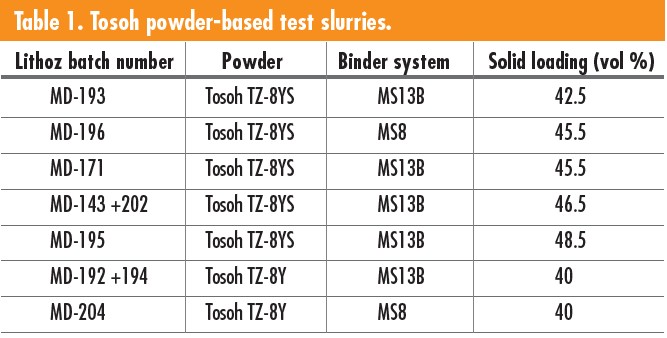
Five YSZ powders from Inframat Advanced Materials LLC (Manchester, Conn.) and Tosoh Corporation (Tokyo, Japan) were tested to determine if they could form viable slurries for LCM component builds. Based on known standard starting parameters, ideal powders were 0.5–1 μm in size with a low surface area of about 5–7 m2/g. Two Lithoz binders—MS8 and MS13B—were tested in conjunction with the YSZ powders. The Inframat powders never resulted in a printable slurry. Both Tosoh powders mixed well with the MS8 and MS13B binders. Seven slurry formulations using Tosoh TZ-8YS or TZ-8Y powders and Lithoz MS13B or MS8 binders were mixed, as seen in Table 1.
Lithium silicate (Li4SiO4) powder was synthesized using a solid-state reaction method. Once ground, the powder was sieved through a No. 270 mesh or No. 325 mesh sieve, and two slurries were made using the MS13B binder: MD-203 (No. 270 mesh, solid loading 48 vol %) and MD-208 (No. 325 mesh, solid loading 51 vol %). MD-203 was not printed because the lithium silicate partially reacted with MS13B binder during storage, causing the slurry to become too viscous for printing.
Printing
Slurries using the MS13B binder printed well when combined with the TZ-8YS powders; in contrast, MS8 binder combined with TZ-8YS powders did not print as well. Solid loading volumes of 42.5%, 45.5%, 46.5%, and 48.5% were all tested. Solid loadings of 45.5 vol % and 46.5 vol % were the ideal mixtures. Tosoh TZ-8YS test slurry with a 45.5 vol % solid loading was used for two prints. The first went relatively well, with the slurry becoming more viscous toward the end of the print (120 layers). The second print reused the residual slurry in the vat of the printer. The second print made it to layer 63 before the slurry was unusable (i.e., it started to partially cure, resulting in increased viscosity), and the print was aborted.
The lithium silicate powders used to make slurry MD-208 had larger than standard particles for printable slurry, resulting in a relatively abrasive or rough slurry. Light penetration was quite high, leading to light scattering, which caused some partial curing around the parts’ edges, evident as clumps. The larger particles also caused nonuniform flow properties in the slurry. The larger particle size and solid loading of 51% resulted in the printed parts being relatively weak compared to similar YSZ parts.
Sintering
The printed YSZ parts were cleaned of residual slurry, dried, and moved into a drying furnace at 120°C for three days. After the parts were preconditioned, some small cracks appeared on the surface of larger, thicker parts.
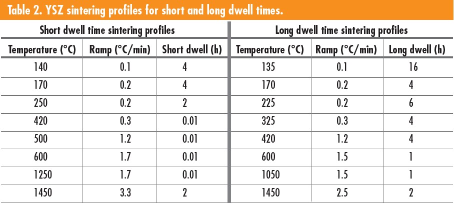
Sintering schedules were adjusted slightly from the first profile seen in Table 2, with the second having longer dwell times at lower temperatures. A temperature of 420°C was used for the binder burnout. Longer dwell times resulted in less cracking and flaking in parts, especially for nonideal slurries such as the 42.5 and 48.5 vol % slurries and the TZ-8YS and MS8-based slurry.
Once fired, the parts with thin walls, such as the turbine found to the right in Figure 1, had no surface damage. The turbine was 18 mm in diameter and 10.5 mm tall. Parts with wide layers, such as the piece to the left in Figure 1, which had printed dimensions 17.5 mm wide and 3 mm tall, resulted in many layers flaking and cracking apart. The Tosoh TZ-8YS samples had cracks between some printed layers, which did not densify during sintering, in contrast to the 42.5 vol %, 45.5 vol %, and 46.5 vol % solid loading slurries. The 48.5% solid loading slurry only resulted in samples that were printed flat to the build plate. Most parts sintered well.
Figure 1. Tosoh TZ-8YS sintered samples, printed from slurry with 42.5% solid loading. Left and center show two common failures (cracking and flaking) and right shows a sample with complex geometry that sintered successfully. Credit: Zaengle
Regarding lithium silicate, these parts had no visible cracking or flaking after printing; however, there were some pinholes on larger samples. During cleaning, the samples had partially cured residue on the edges of the parts. The binder’s weak bonding allowed the sharp edges of samples to become rounded during cleaning. Overall, parts stayed intact with no significant flaws and there were no difficulties removing them from the build plate or cleaning. Figure 2 shows examples of cleaned samples before placement in an oven for preconditioning. Parts preconditioned well; no surface cracks were visible once complete.
Figure 2. MD-208 lithium silicate parts cleaned before preconditioning. Credit: Zaengle
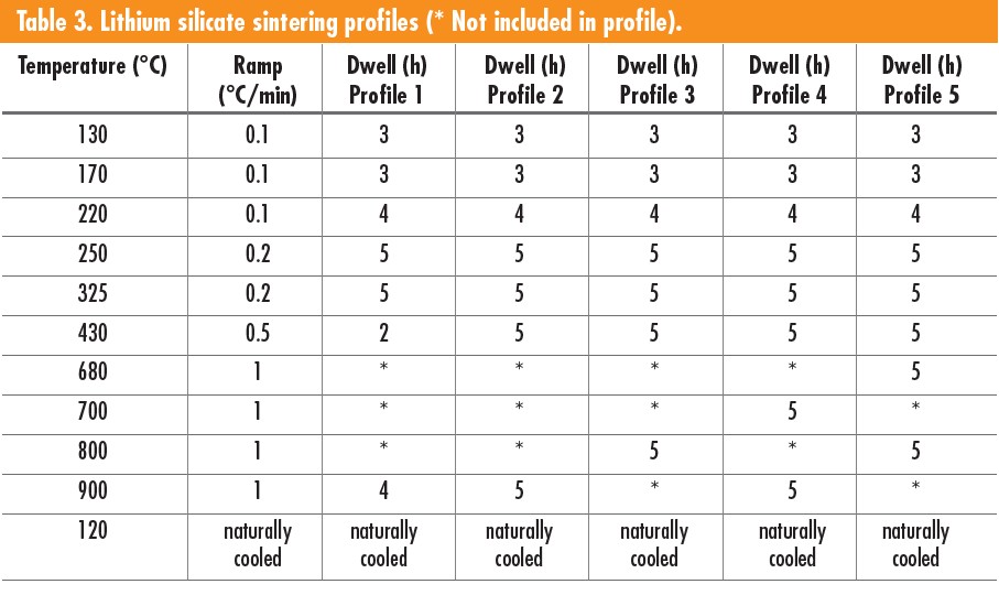
As shown in Table 3, five sintering profiles were tested, ranging from seven to eight steps. Sintering temperature and dwell times were varied over a narrow range to improve density in the final parts. The fourth and fifth profiles included a step between binder burnout and sintering to heat any unreacted precursors in the material.
Because parts were printed, layers were perpendicular or parallel to the disk face. All the samples had signs of bubbling on the surface after sintering; however, samples printed with the layers perpendicular to the disk’s large face had noticeably less bubbling. Additionally, samples with smaller surface area layers had noticeably less bubbling, with only the side facing up during sintering developing surface bubbles. The larger surface area between layers led to more bubbling on the surface, as shown in Figure 3, which was sintered at 900°C.
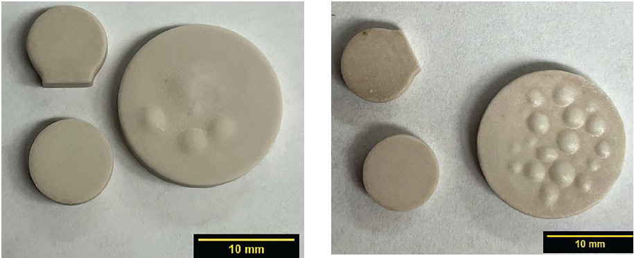
Figure 3. Lithium silicate samples sintered using Profile 4 from Table 3. Left shows the sample top; right shows the sample bottom. Credit: Zaengle
The samples in Figure 4 were sintered at a lower temperature of 800°C. The samples sintered using profiles 4 and 5 had noticeably more surface bubbles than the first three profiles tested. Profiles 4 and 5 had an additional thermal treatment segment compared to the other profiles.
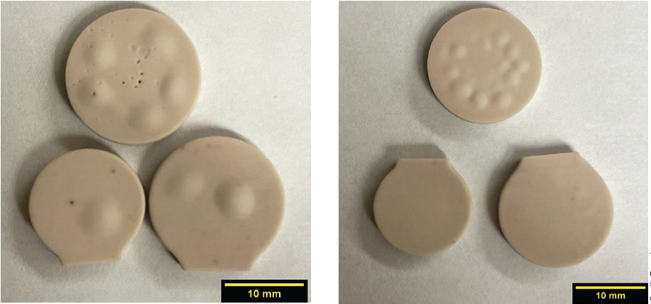
Figure 4. Sintered lithium silicate from sintering profile five top (left) and bottom views (right). Credit: Zaengle
The samples shown in Figure 4 with the small foot were the two densest parts at about 90% of actual density. The segment held at temperatures in the solid-state reaction range was used to make the base powder. The profiles then ramped to a final sintering temperature. The additional step was to provide more time for the samples at an elevated temperature to react, causing CO2 off-gassing from the leftover precursors used in solid-state reaction. The CO2 was believed to cause bubbling, primarily affecting the sample’s top-facing surface.
Grain size and density
The two particle sizes of Tosoh powders produced samples with different grain sizes (Table 4). The larger TZ-8YS powders resulted in smaller average grains at 2.7 μm, whereas the TZ-8Y powders displayed more grain growth with an average of 5.3 μm.
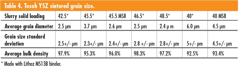
The sintered TZ-8Y parts had several minor features on the surface compared to the TZ-8YS parts. An example of the feature variation is the presence of small humps on the visible grains’ surface. The TZ-8YS grains had prominent features compared to the features seen on the surface of the TZ-8Y samples. The surface variation between the TZ-8YS and TZ-8Y parts shows some correlation between solid loading and particle sizes of the base powder. The TZ-8Y samples had larger grains with a slightly lower density of 93% vs. 97% for the TZ-8YS samples. Figure 5 is an example of the layering from the 3D printing process that remains on the surface of the YSZ parts even after sintering. Figure 5 also includes a close-up of a microcrack in the ceramic structure (left). Figure 6 shows examples of the YSZ surface microstructure. Both have small pores throughout the microstructure.
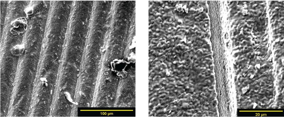
Figure 5. Layered microstructure of sintered YSZ parts. Credit: Zaengle
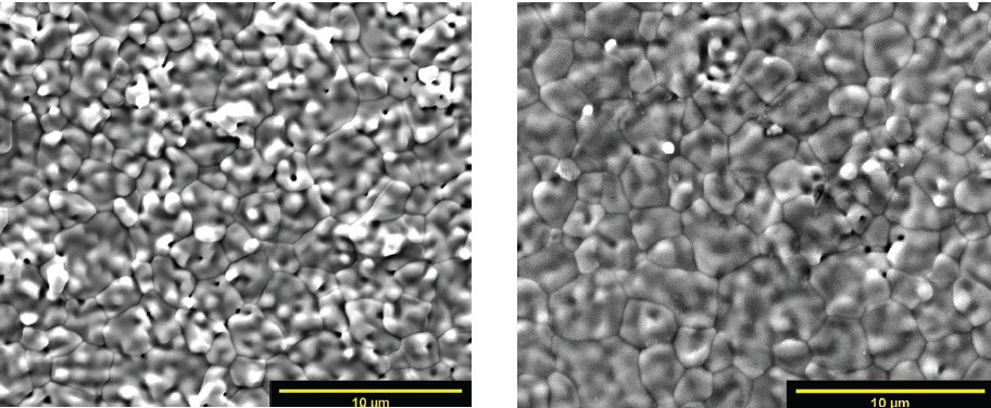
Figure 6. Flat surface microstructure of sintered YSZ parts. Credit: Zaengle
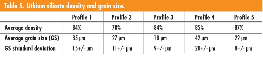
The sintering profiles of the lithium slurries were adjusted to improve bulk density and average grain size. Table 5 shows how the sintering profiles affected density and grain size. The dwell time for debinding, sintering temperature, and dwell, and later a reaction temperature and dwell were altered to improve density and grain size. Profile 5 yielded the best results for density with an average of 87%, and the highest parts density was 90%. The samples with a lower surface area between layers relative to size resulted in the best density. Samples subjected to higher sintering temperatures of 900°C resulted in larger grain sizes, as seen in profiles 1, 2, and 4, where 3 and 5 sintered at 800°C. Profiles 4 and 5 with an additional step at 680°C or 700°C showed improved density and grain size.
When the first three profiles were tested, the sintering temperature and debinding dwell alterations had minimal effect. Profile 4 and 5 included a step to react any carbonates remaining in the material, which improved density and grain growth. The left of Figure 7 corresponds to the first three profiles and shows pinholes or an open structure. The right of Figure 7 is an example of the microstructure seen in the last two profiles that have improved grain growth and density.
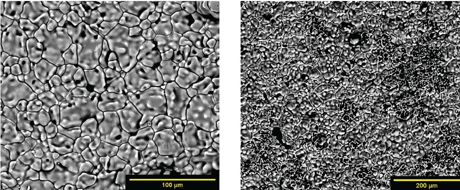
Figure 7. Lithium silicate sintered part using profile three (left) and profile four (right). Credit: Zaengle
Conductivity and activation energy
Impedance spectroscopy was used to determine the activation energy of 3D-printed YSZ and lithium silicate samples. The key features tested were layer orientation to determine if there were any effect on the conductivity and activation energy of the material. AM YSZ samples resulted in a bulk conductivity average of 1.33 × 10⁻³ Ω-cm at 300°C. AM lithium silicate samples resulted in an average bulk conductivity value of 5.14 × 10⁻⁵ S cm–1 at 300°C compared to Adnan et al.,12 who reported a conductivity value of 1.16 × 10⁻⁴ S cm–1 at 100°C. The conductivity values were less for the AM parts compared to monolithic parts given the reported values were recorded at lower temperatures.
Table 6 compares the bulk experimental averages found in the literature.11,26 The bulk activation energy for both lithium silicate layer orientations resulted in 0.22 eV. However, the surface orientation had slightly higher bulk resistance values compared to the layered orientation. The same bulk resistance variation was observed in the YSZ samples, with somewhat higher resistance values for surface orientation samples than layer orientation samples. The bulk activation energy for the two YSZ compositions had a 0.1 eV difference, with the TZ-8Y samples having higher activation energy. Both YSZ and lithium silicate materials demonstrated no significant direct effect on electrical properties caused by varying layer orientation during printing and electrode placement.
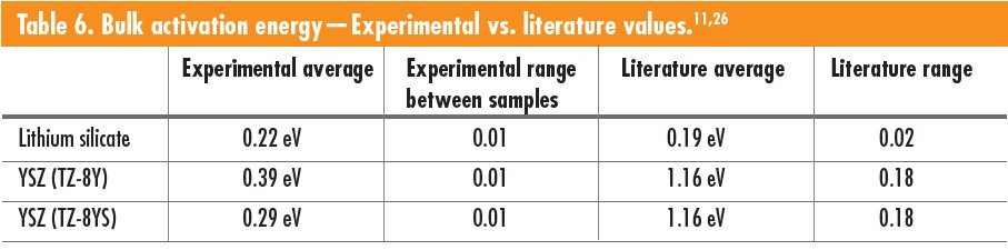
Lithium silicate experimental activation energy was determined for the temperature range 125–300°C with a printed layer thickness of 100 μm. A 100-μm-layer thickness is relatively high compared to typical LCM layers. The experimental average bulk activation energy for lithium silicate was 0.22 eV. The lowest recorded bulk activation energy found was from Adnan et al.,11, which was 0.19 eV for samples prepared by sol-gel, pressed into pellets and sintered. The 3D-printed lithium silicate samples had high porosity with an average density of roughly 85% and large outgassing from unreacted precursors, creating large-scale disconnectivity and defects in the materials, thus increasing the activation energy.
YSZ experimental activation energy was determined for a temperature range from 300–500°C with a printed layer thickness of 25 μm. The practical average bulk activation energy was 0.34 eV, with Kwon et al.,26 reporting bulk activation energies of 1.16 eV. The lower activation energy for the experimental 3D-printed and sintered material may be attributed to electrons potentially finding a path of least resistance not found in traditionally formed parts. The layering may lead to microcracks in the bulk material and uneven sintering, leading to stresses in individual layers, also causing delamination. The thermal profile does not separate debinding from sintering, combining both processes into one. Debinding may be causing tunneling in the microstructure from the escaping binder gases during sintering, leading to a nontraditional microstructure.
Conclusions
Five YSZ powders with two binder systems were tested at varying solids loading percentages. Two powders, the Tosoh TZ-8YS and TZ-8Y and the Lithoz MS13B and MS8 binders, resulted in printable slurries. Seven total variations were successfully printed and sintered. The TZ-8YS powders with a solid loading of 45.5–46.5% matched with MS13B binder were determined to be the ideal slurry for 8 mol % YSZ. The best-sintered densities achieved for the Tosoh slurries was 98.3% for TZ-8YS and 93.4% for TZ-8Y.
Five batches of lithium silicate powder were made, resulting in two lithium silicate slurries. The binder used was Lithoz MS13B. The slurry formulations resulted in high curing depths and solid loading amounts. However, the slurry tended to cure when mixed, so working times were limited to one week. One lithium silicate slurry was successfully printed and sintered. The slurry contained 51% solid loading and MS13B binder. The best-sintered density for the lithium silicate slurries was 87%.
Samples printed with different layer orientations were tested to determine any significant bulk conductivity variations and activation energy variations using impedance spectroscopy. There was no direct evidence of layer orientation having substantial effects on tested samples’ bulk conductivity and activation energies. Preliminary characterization was used to determine how effectively parts could be printed. Micro surface cracking, surface bubbling, and activation energies for conduction revealed a significant difference between traditional manufacturing and AM. These results demonstrate that these materials can be successfully 3D printed and sintered to produce dense products.
Acknowledgments
The authors wish to acknowledge the assistance of The New York State’s Division of Science, Technology & Innovation; Empire State Development’s FuzeHub Advanced Manufacturing Grant; and the Inamori School of Engineering for teaching assistant support for J. T. Zaengle. Professor S. K. Sundaram acknowledges the support by Kyocera Corporation in the form of Inamori Professorship, and Lithoz America for their assistance in slurry development.


Related Articles
Bulletin Features
The nonferrous metals market: Supply and regulatory pressures inspire strategies for a resilient future
Nonferrous metals serve foundational roles in the electrification, renewable energy, and digital transformation. Nonferrous metals are metals that do not contain iron in significant amounts. These metals typically are nonmagnetic, corrosion resistant, electrically and thermally conductive, and lightweight, making them ideal for applications in the emerging markets mentioned above. Even…

Market Insights
Industrial digitalization: ‘Smart’ operations can improve worker safety and well-being in high-temperature environments
Heavy industry is the backbone of economies around the world, critical to automotive production, construction, the energy sector, and everything in between. But many heavy industries are facing worker shortages. There are more than 400,000 open manufacturing jobs in the United States, according to the Bureau of Labor Statistics.1 With…

Market Insights
‘Fail fast’ manufacturing: How disciplined experimentation strengthens, not threatens, quality
In manufacturing, few phrases raise eyebrows faster than “fail fast.” In the startup world, this business strategy is celebrated as a sign of agility. On a ceramic manufacturing floor, it can sound careless or even dangerous. In manufacturing, few phrases raise eyebrows faster than “fail fast.” In the startup world,…