
A fluid catalytic cracking unit (FCCU) is the heart of most oil refineries. It is here where much of the profit of a refinery can be made. This unit transforms low-value bottom-of-the-barrel tars with high molecular weights into high-value, profitable high-octane fuels and petrochemicals by breaking down the hydrocarbons.
Fluid catalytic cracking is a secondary refining process that uses catalysts to produce high-octane gasolines, olefinic gases and other petroleum products. About one third of all the crude oil processed at a refinery with a FCCU is refined in this unit, making it a valuable asset. At present, there are about 135 refineries in operation in the United States. Refractory selection for FCCUs depends on where in the processing unit the refractory is placed.
In general, refractories are strong and dense, or light and soft. Every combination exists in between, and there are always trade-offs between properties to consider when selecting refractories. Determining which of a wide variety of refractories to use in a specific area can be quite challenging. Some areas require abrasion resistance, while others need to have a better insulating effect. It helps to simplify the task and break down the unit into four main areas: the riser, cyclones, reactor and regenerator, and transfer lines. These areas are pointed out in Figure 1, along with other specific areas mentioned below.
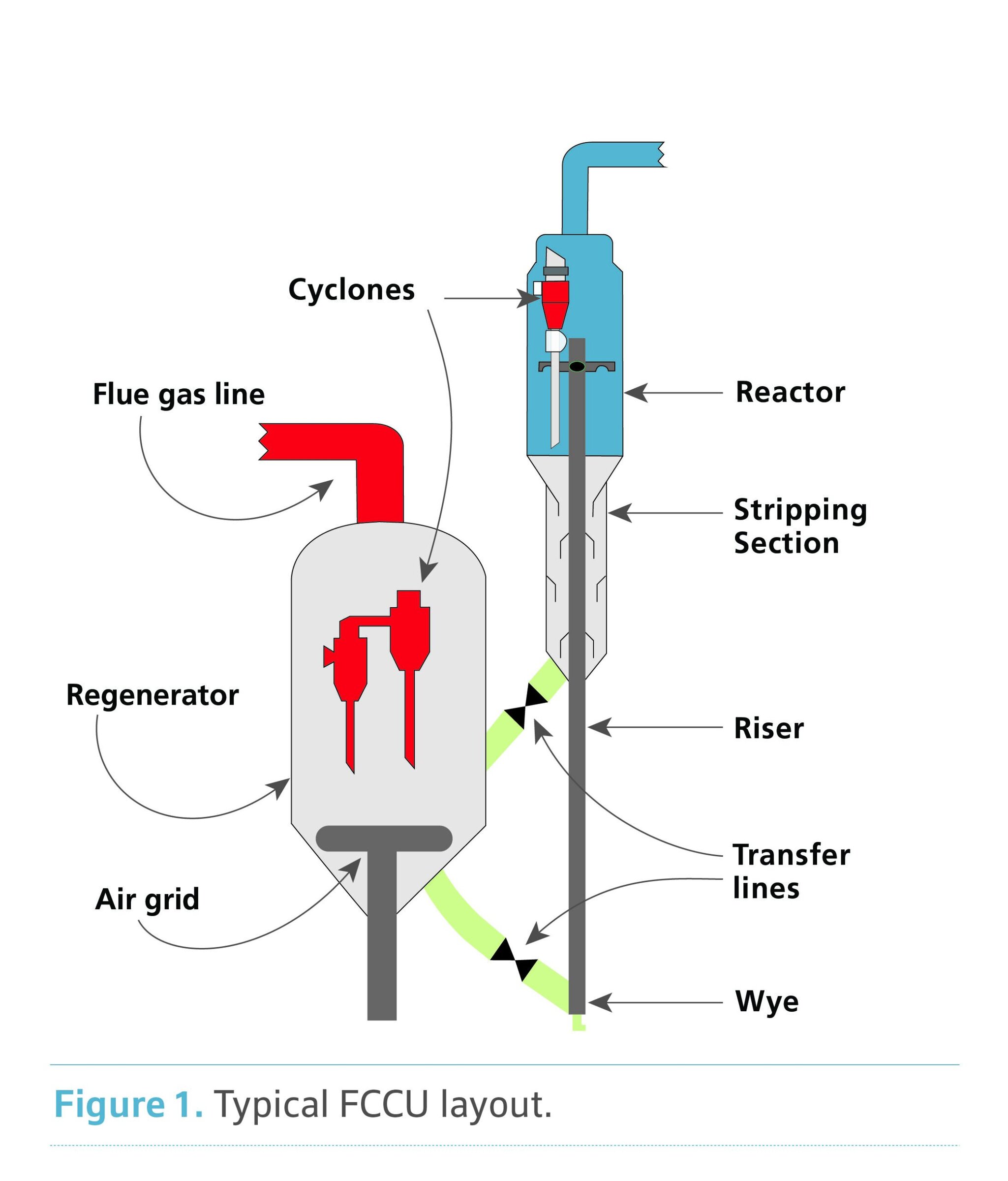
Figure 1. Schematic of fluid catalytic cracking unit showing the primary components requiring refractory. Credit: HWI
Risers, regenerators, and cyclones
In the riser, hot catalyst feeds in from the regenerator and is fluidized and blown upward using air. Long-chain hydrocarbons, such as asphaltene and other tar-like oils, are preheated and sprayed into the fluidized catalyst. With heat and aid of the catalyst, the hydrocarbons crack and break down into shorter hydrocarbon chains such as gasoline or propylene, which are much more profitable for a refinery than the original long-chain hydrocarbon feed. This reaction also produces excess carbon that deposits on the surfaces of catalyst particles. The conditions created in the riser with this process can be hellishly extreme, so it is often a difficult area for solving refractory problems. A great deal of refractory abrasion results from the high gas velocities used to fluidize and blow the catalyst and feed upward. The heat created from the catalyst is also a concern, but the reaction is endothermic, and therefore, having the best insulation is not necessarily a primary factor.
The refractory lining in the riser is about six inches thick on the walls and is usually gunned into place. In general, the riser will need refractory with very good abrasion resistance; some specific areas will need even more thickness. As mentioned, the lining will also need more insulating value where it is possible and makes sense. For the most part, abrasion resistance of products used in risers should be rated at 10 cc loss or less (after firing to 1,500°F, tested with ASTM C704/ C704M-151). The lower the loss value, the more abrasion resistant the refractory. Figure 2 shows an example of samples after abrasion testing.
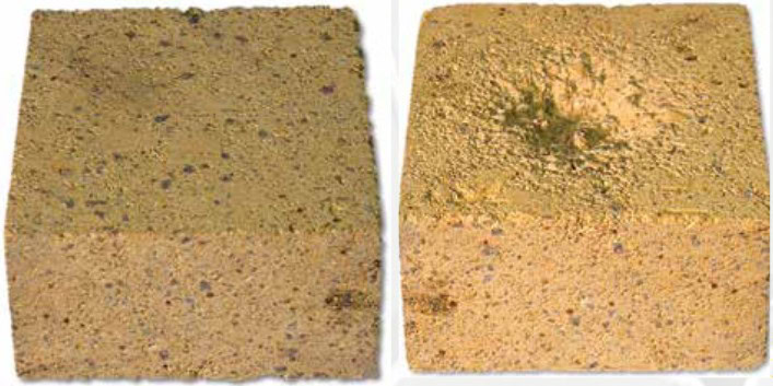
Figure 2. Before (left) and after (right) refractory abrasion testing in accordance with ASTM C704 protocol. The example shows 11.5 cc loss on a Clipper DP refractory brick used for test demonstration purposes. Different refractories are used in abrasive situations such as the riser and should be rated at 10 cc loss or less. Credit: HWI
Density is generally used to assess the insulating value of refractory; the lighter a refractory is the more insulation it will provide. But the lighter it is, the less strength and abrasion resistance it will have. In the riser, products with densities about 135 pounds per cubic foot (pcf) and higher are used. In areas of the riser with especially extreme wear, such as the wye section corners or injector nozzles, products with densities from 160 to 180 pcf with abrasion resistance of 6 cc loss down to 3 cc loss are frequently used. Other properties, such as cold crushing strength (CCS) and thermal conductivity, generally relate to abrasion resistance and density, respectively. These properties are also important, but for the sake of narrowing down the options, abrasion resistance and density are the major factors.
Also important is permanent linear change (PLC, shrinkage or expansion after firing), typically measured after firing 1,500°F using ASTM C113-14.2 This property should almost always be a maximum of –0.3%; the closer to 0%, the less shrinkage cracking and other issues will arise during operation. This applies to all areas of the FCCU. Most products that meet this PLC requirement also will be capable of operating in the temperature ranges found inside most FCCUs, but PLC should be double-checked when selecting refractory for any area.
The riser typically feeds directly into two sets of cyclones inside the reactor vessel. The function of the cyclones in the reactor is identical to those in the regenerator: to filter catalyst particles from the hydrocarbon products (in the reactor) or the flue gas (in the regenerator). This is done by swirling the catalyst and gases inside the cyclone at high speeds and using centrifugal force to swirl catalyst particles downward, while the gases exit through the top and into the next set of cyclones, or on to the next processing vessel. The conditions created by all this centrifugal force and particulate creates an extremely abrasive environment at temperatures in the 1,000–1,200 °F range. For this reason, the cyclones have an internal layer of abrasion-resistant refractory that is usually only one inch thick. The density of the product installed inside the cyclones is irrelevant because they are contained inside the reactor or regenerator and do not require any heat insulation.
Refractory selection for changing conditions
Refractory selection in cyclones is based primarily on choosing the best abrasion resistance possible, but other concerns like ease of installation are also a factor. The type of refractory used here is nearly always a phosphate-bonded ramming type product. These are often referred to as plastic refractory products and are installed using a mallet or pneumatic ramming tool into hex-mesh, s-bar, or k-bar anchors. Typical plastics come premixed in slabs that can be rammed into place right out of the box with plenty of working time before they set. The downside is that they are usually heat-setting and may require some sacrificial support that will burn out during the initial firing, especially when installed overhead. Another concern with this type of phosphate-bonded plastic is that typical formulations are water soluble until fired above 650°F. So FCCUs that are started-up with steam can cause damage to this type of refractory unless treated to 650°F first.
Other types of phosphate-bonded products are designed to set exothermically at ambient conditions. These are shipped dry in a bag and mixed onsite with a special acidic solution or water to the desired consistency. The advantage of these types of materials is that they form water-insoluble linings that are resistant to the steam that might be used during startup. The disadvantage is that these materials can be very difficult to install because the set time is usually less than 15 minutes. This can lead to wasted time and material.
Regardless of which type of phosphate-bonded refractory is selected, the critical property to meet is abrasion resistance. This should be maximized as much as possible, so a maximum of 4 cc loss is often the acceptable threshold. Areas with the worst abrasion resistance, particularly the areas immediately around the cyclone inlet, should be even less with a maximum of 2 or 3 cc loss. Materials with this level of abrasion loss typically have densities of about 170 to 180 pcf, but the density is irrelevant if the proper abrasion resistance is achieved. Phosphate-bonded products are frequently used in cyclones because these products achieve excellent strengths at the temperatures experienced here, ~1,000°F. Most cement-bonded products have weaker strength in this moderate temperature range, but greater green and high-temperature strengths, in addition to a wider variety of installation options.
As described, the cyclones are contained within the reactor and regenerator. The catalyst falls out the end of the cyclones through tubes called dip-legs into a collector at the bottom of the vessels. In the bottom of the reactor, the catalyst falls over a series of baffles to interact with steam that is injected from the bottom and rises upward. This steam strips extra hydrocarbons from the catalyst before the catalyst enters a transfer line to the regenerator. In the regenerator, the carbon on the catalyst burns off, which requires that the temperature in this vessel is hotter, typically around 1,500°F and up to 2,000°F. The catalyst is fluidized with an air grid on the bottom of the regenerator, and the cyclones separate flue gases from the catalyst. The catalyst collects at the base of the vessel, below the air grid. The conditions in both these vessels are less severe with respect to abrasion, particularly in the walls. This means that more insulating refractory products can be used over stronger, denser options. There are still areas with some abrasion issues, particularly in the bottom of each vessel where the catalyst collects and rubs the refractory.
In the walls of the regenerator and reactor where abrasion is lightest, a lighter weight product should be used, but some strength is still needed for long-term reliability. The density of refractory in these areas should be 70 to 90 pcf with a CCS greater than 1100 psi (after firing to 1,500°F). The refractory does not necessarily have to be abrasion resistant, so the CCS property is used to determine the strength. Using insulating refractory in the walls helps keep the heat inside the system. Too much heat loss can create problems, though some designs of FCCUs incorporate special parts off the regenerator designed to cool the catalyst to a specified temperature. As for the bottoms of these vessels where the catalyst collects, refractory selection must find a balance between density and abrasion. Middle-weight products have been designed to work very well in these areas. They provide both low thermal conductivity and abrasion resistance but do not necessarily excel at either. These products should have a density of 100 to 130 pcf with an abrasion resistance rated to less than 12 cc loss.
Connecting all these vessels together are transfer lines. These lines contain and control the flow of catalyst between each part of the process. Slide gates in the transfer lines control the flow. Transfer lines also have some tricky thermal expansion to address between the different vessels created, so complex expansion sections are used to account for it. All the refractory on the transfer line walls should be both insulating and abrasion resistant, same as the bottom sections of the reactor and regenerator. The slide gates often experience more wear from abrasion, but also do not require as much insulation, so higher density products can be used for them.
The refractory properties required in transfer line walls are very similar to those in the reactor and regenerator. A middle-weight product with a density of 100 to 130 pcf with an abrasion loss of less than 12 cc is ideal. For the slide gates, similar products as those used in the cyclones can be rammed into hex-mesh anchoring. Products with 5 cc abrasion loss or less will work well.
Proper refractory selection in the FCCU is critical to the operational requirements and overall reliability of the unit. Understanding the conditions present inside each area is just as important as understanding the properties of refractories and how they work under those conditions. Every FCCU operates differently, and conditions in one unit may be more or less severe than the next. Refractory selections should be tailored to combat special situations in each piece of the process to provide great insulating value in addition to excellent abrasion resistance and achieve the optimal balance of properties.

Related Articles

Market Insights
Engineered ceramics support the past, present, and future of aerospace ambitions
Engineered ceramics play key roles in aerospace applications, from structural components to protective coatings that can withstand the high-temperature, reactive environments. Perhaps the earliest success of ceramics in aerospace applications was the use of yttria-stabilized zirconia (YSZ) as thermal barrier coatings (TBCs) on nickel-based superalloys for turbine engine applications. These…

Market Insights
Aerospace ceramics: Global markets to 2029
The global market for aerospace ceramics was valued at $5.3 billion in 2023 and is expected to grow at a compound annual growth rate (CAGR) of 8.0% to reach $8.2 billion by the end of 2029. According to the International Energy Agency, the aviation industry was responsible for 2.5% of…

Market Insights
Innovations in access and technology secure clean water around the world
Food, water, and shelter—the basic necessities of life—are scarce for millions of people around the world. Yet even when these resources are technically obtainable, they may not be available in a format that supports healthy living. Approximately 115 million people worldwide depend on untreated surface water for their daily needs,…