
The role of glass in modern society is evident everywhere—from windows and wine bottles to car windshields and durable device touchscreens.
Industrial glass manufacturers require highly engineered high-temperature furnaces to contain glass in its molten state (3,000°F–3,200°F, or 1,600°C–1,800°C) so that convections in the melter allow proper mixing as well as melting of incoming raw batch materials. After the refining process, in which dissolved gases are allowed to escape, the glass has a chemical homogeneity ready for formation of the final article. This molten glass must be contained by a refractory lining in the furnace to allow safe operation over an extended time period to economically and efficiently manufacture high-quality glass products.
Evolution of glass furnace refractory linings
Toward the end of the 19th century, fireclay, a bonded alumina refractory, was the glass furnace refractory lining of choice. This progressed to a better quality of fireclay, and later, the refractory lining package included bonded silica brick, which easily dissolved but did not affect glass quality. However, the furnace life of glass-contact silica refractory was only 8–12 months.
In the early 20th century, sillimanite (Al2O3 ∙ SiO2) and then mullite (3Al2O3 ∙ 2SiO2) found their way into use as bonded refractory materials that performed better than fireclay and silica bricks.1,2 Typically, these refractory materials are pressed with binders to maintain geometry and fired at high temperatures to create a bonding phase for strength. These refractory bonded shapes typically have a porosity (~10–15%) that will severely reduce corrosion resistance in contact with a slag or glass at high temperatures, not to mention high solubility of their components.
Enter the advent of a refractory manufactured by fusing molten oxide powders at high temperatures (~3,800°–4,000°F). The process of fusion casting bypasses conventional bonding of refractory bodies mentioned earlier by developing crystalline intergrowths capable of exceptional corrosion resistance due to high density of the body. The batch, after dry blending, is fed to an electric arc furnace for fusion by energy released in arc-resistance paths. The furnace melting the material tilts to pour this liquid into molds designed for final applications.3 Monofrax LLC pioneered this technology in the late 1930s with high-alumina fused cast refractory materials and, later, many compositional evolutions.
After the Second World War, the refractory of choice for lining glass furnaces soon became a material called AZS, an acronym for a composition consisting of alumina, zirconia, and silica. Manufacture of fusion-cast AZS resulted in a refractory material with low porosity (~1%), high density, and good corrosion resistance—critical factors to extend life of the glass furnace. The material increased furnace life from ~18 months to 3–5 years, allowing furnaces to operate at higher temperatures and at greater throughput.1,2
Corrosion resistance of AZS results from its low porosity and high density, as well as the presence of zirconia, a highly insoluble phase. Even though the AZS refractory lining in contact with glass extends high-temperature glass furnace life dramatically over bonded refractory materials, furnace life cannot continue indefinitely. Corrosion and erosion of the lining will occur, eventually curtailing furnace operation until the lining is repaired or replaced. Figure 1A shows a new AZS furnace lining before delivery and installation, contrasted with a corroded AZS furnace lining after 6.5 years of service in a soda-lime glass furnace in Figures 1B and 1C.
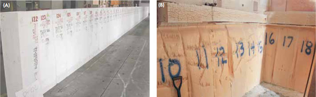
Figure 1. (A) New AZS furnace lining during inspection before delivery and installation. (B) Corroded AZS furnace lining after 6.5 years of service in a soda-lime glass furnace. Credit: Monofrax
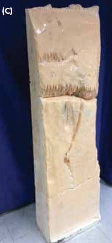
Figure 1. (C) Close-up of a corroded AZS furnace lining panel after 6.5 years of service in a soda-lime glass furnace. Credit: Monofrax
Glass quality in soda-lime, borosilicate, and high alumina–silica glass compositions is critical to achieve clarity and strength because, without these properties, the items of interest will fail in their designed applications. This places high demand for quality refractories in contact with glass to not alter critical properties of the glass by refractory defects and dissolved refractory components. The images in Figure 1 of corroded AZS fused cast refractory lining are a revealing testament to the erosion of refractory linings during a glass furnace campaign.
The final glass article, be it a bottle or window, will actually have some trace of the refractory components (e.g., ~0.07% ZrO2) dissolved in its structure, although at a level that does not affect required glass clarity and strength. Refractory lining in a typical glass furnace is designed to account for the types of corrosion encountered at molten glass contact or by corrosive vapor species in non-glass contact regions at temperatures of ≥2,700°F (1,500°C).
The philosophy in glass furnace refractory design is to ensure corrosion equivalency of differing refractory materials in the whole furnace, so the term of the campaign is not prematurely interrupted due to a single refractory region failure.
There are many compositional varieties of fusion-cast refractories available beyond AZS, such as high zirconia, high alumina, magnesium spinel, and chrome–magnesium–aluminate castings. Monofrax LLC supplies several compositional groups (~12 currently) to diverse glass manufacturing industries, including flat glass, containers, fiberglass, and, more recently, tough, thin glass touchscreen surfaces for electronic devices.
AZS fused cast materials such as Monofrax CS-3 and CS-5 are typical glass contact and non-glass contact materials, while high-alumina materials such as Monofrax M and H are used in lower temperature glass contact refiner and distributor regions. Chrome/alumina/magnesia-bearing materials, such as Monofrax K-3 and E, are often used in weir walls and throat cover blocks, which require the highest level of corrosion resistance and can tolerate potential chrome coloration.
Clarity to containment
On December 2, 1942, a team of 49 scientists, led by Enrico Fermi, proved that a self-sustaining nuclear chain reaction could be initiated. Conducted under Stagg Field of the University of Chicago, this experiment, called the Chicago Pile-1 reactor, became the integral first step of the Manhattan Project to develop the atomic bomb.4
In the midst of this dash to successfully create a controlled nuclear chain reaction, there is no known reference that any of these scientists foresaw the immensity of the amount of nuclear waste that harnessing such energy in weaponry and power generation would create.
However, as of January 2009, the amount of spent nuclear fuel from the 104 nuclear reactors operating within the United States alone reached 64,000 metric tons.5 In the U.S., defense and weapon-related activities are another source of waste, with the largest quantities created in the early days of nuclear weapon development and testing.
The U.S. Department of Energy officially discontinued reprocessing spent nuclear fuel in 1992, although the U.S. has generated 347,300 m3 of waste incidental to reprocessing.6 Most of this liquid high-level waste (HLW) is stored in underground tanks at the Hanford site in Richland, Wash., and the Savannah River site in Aiken, S.C. Another portion of HLW was calcined to a dry powder and is stored at the Idaho National Laboratory in Idaho Falls, Idaho.
Weapons-grade plutonium production stopped in the 1980s. However, the consequence of this material lingers on in the form of waste. The current emphasis of nuclear fission is electricity generation in the U.S., but not to the extent of its role in other countries, such as Canada and China.
In the public sector, developing uranium fuel to produce power from nuclear plants generates different forms of waste (e.g., mine mill tailings, conversion, enrichment)—which all will need disposal. Rod Ewing7 states that “…the complexity of the nuclear waste disposal problem has delayed final choices of waste disposal sites in most countries that have nuclear waste inventories. So much so that, there are, at present, no operating [geologic] nuclear waste repositories for spent nuclear fuel from commercial nuclear power plants or for HLW from the reprocessing of spent fuel.”
Complexity in the disposal of nuclear waste is partially due to the variety of waste compositions that ultimately drive the need for different glass containment formulations. Waste containment plant designs are dictated by radioactive loads, which may require fully remote designs or permit a hands-on approach. At the Hanford and Savannah River sites, HLW is further separated into a smaller volume containing most of the radioactivity and a larger volume of contaminated liquid with much lower radioactivity (low activity waste, or LAW), which has a different disposal strategy. However, each facility treats LAW differently—Savannah River grouts LAW, while Hanford vitrifies it. Regardless of the means, nuclear waste must be reduced to a solid form before disposal and must resist leaching.
Vitrification
The term vitrification connotes involvement of glass, which serves as a host medium to stabilize radioactive waste. Durability is the top priority for containing radioactive waste for thousands of years. This contrasts with other applications, such as commercial glasses designed for optical clarity.
At Savannah River and Hanford sites, radioactive waste is transitioned into a molten borosilicate glass through a variety of steps involving a liquid slurry with dry additives that form a blanket on the glass called a cold cap. The bottom portion of this cold cap melts into a foamy glass and ultimately melts into the pool, which is poured into a robust stainless steel canister (~1–3 m high) and allowed to cool, forming a solid matrix.
Containers are welded shut, ready for storage and final disposal. This encapsulation in molten glass and solidification in final storage containers is called vitrification and is a suitable and adequate process for management of ILW and HLW.
Figure 2A shows a K-3 melter box in the setup area at Monofrax with a similar layout to soda-lime industrial glass tanks. The melter box contains glass slurry as nuclear waste is encapsulated within the glass. This box is a portion of the larger unit at the Hanford site (Figure 2B).
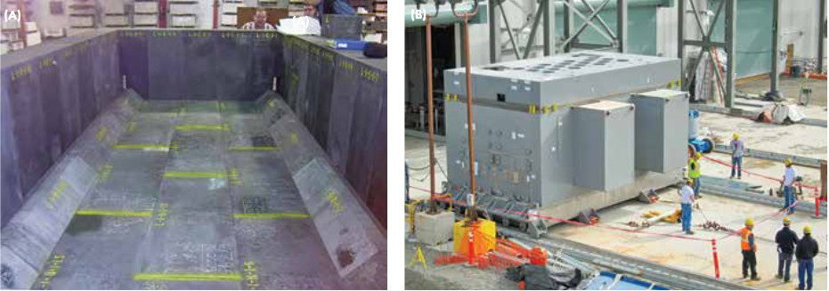
Figure 2. (A) A melter box consisting of Monofrax K-3 during inspection before shipment to the Hanford site. (B) Low activity melter unit containing K-3 melter box being readied for use at Hanford. Credit: Monofrax
Refractory design experience, philosophy, and technology for melting of industrial commercial glasses (e.g., soda-lime, borosilicate, and high-alumina cover glasses) has been transferred in a similar fashion when designing the nuclear waste vitrification melter. In this case, the design uses another property of glass.
Unlike the clarity and strength necessary in soda-lime and borosilicate glass, the chemistry of encapsulating glass in nuclear waste treatments is unique in its ability to immobilize radionuclides. Specific oxides determine various properties in soda-lime glass, such as melting point, mechanical properties, or color. For example, iron is incorporated at low levels (0.1–2.0% iron oxide) in soda-lime glass to reduce the effect of harmful UV rays for construction glass.8
Design of the glass composition necessary for nuclear waste encapsulation involves a complicated selection process with non-radioactive glass-forming additives. These chemistries are tailored to create a favorable viscosity–temperature relation, meaning radionuclide volatilities are not in play.9 In this case, boron has an important role in reducing glass viscosity at temperatures below radionuclide volatility temperatures of >1,200°C.
Vitrification is a particularly attractive immobilization route because the glassy product has high chemical durability.10 Borosilicate glass contains waste material through direct chemical incorporation into the glass structure (i.e., dissolution), although some studies also have evaluated the feasibility of physically encapsulating solid wastes. The durability of borosilicate glass allows storage for thousands of years, even under conditions of irradiation by incorporated radioactive materials, which do not crystallize the oxide glass.
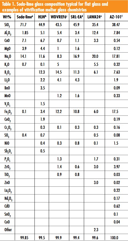
The temperatures encountered in vitrification melters (~1,050°C–1,200°C) are considerably lower than in commercial soda-lime glass tanks (~1,500°C–1,600°C). Table 1 lists soda-lime glass compositions typical for flat glass, alongside some examples of vitrification melter glass chemistries.
There are numerous critical components of the vitrification melter used to heat glass to 1,050°C–1,150°C, not the least of which is the refractory lining. Monofrax has manufactured a chrome-bearing fused cast refractory designed for this lining for over 30 years, since the beginning of the process of encapsulating nuclear wastes. In one instance at Savannah River National Laboratory, the designed life of this lining was estimated to be 2–6 years.11 However, in actual practice at SRNL, the life of Melter #1 was 8.5 years and Melter #2 was >14 years, eventually shutting down due to mechanical failures that were not refractory related.12
Types of nuclear waste
- HLW = High level waste—highly radioactive due to reprocessed nuclear fuel
- ILW = Intermediate level waste—requires shielding when handling
- LLW = Low level waste—contaminated by radioactive materials, but not inherently radioactive
Corrosion in soda-lime glass tanks
Corrosion kinetics and byproducts of fused cast refractories in contact with soda-lime glasses of the container and flat glass industries are well known. AZS refractories have three microstructural components: zirconia dendrites, a coprecipitate component of zirconia and corundum, and a high-alumina glass.
When the AZS lining interacts with molten glass, there is typically a corrosion reaction layer at glass contact that remains attached to the lining. Continued corrosion takes place by erosion of this layer and, in some cases, may “peel” off, creating some glass quality problems.
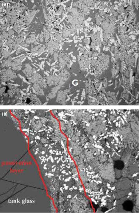
Figure 3. Electron micrographs of (A) virgin AZS and (B) corroded AZS. Credit: Monofrax
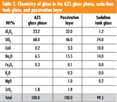
This thin reaction layer, often called the passivation layer (“G” in Figures 3A and 3B) because it serves to “passivate” further corrosion, is a byproduct of incongruent dissolution into the tank glass. Alumina in the coprecipitate alumina–zirconia component of AZS goes into solution at the glass–refractory interface, creating a layer of highly aluminous glass with undissolved zirconia (Figure 3 and Table 2).
Corrosion with soda-lime glass is not restricted to the immediate glass contact, however, as the glass phase component of AZS provides a pathway for diffusing alkali and alkaline earth species, such as potassium, sodium, magnesium, and calcium. Alkalis are more rapid diffusers than alkaline earths, as observed by Kasselouri et al.13 as well as others—potassium and sodium species migrate to deeper depths than magnesium and calcium. Consequently, alkalis such as potassium and sodium promote corrosion of the corundum primary phase at depths into the AZS body beyond the immediate glass–refractory contact.
Corrosion in vitrification melters
Facilities active in vitrification of nuclear waste cannot afford failure of the melter due to refractory lining failure either by excessive corrosion or spalling. During the life of the melter, different glasses formulated due to differing waste compositions can have a variable impact on the refractory corrosion rate. Care must be taken to not formulate glasses that will be highly aggressive to the refractory.
Some of the most corrosion-resistant refractory materials available contain chromium oxide as a major component (e.g., Monofrax K-3 and E). Since the beginning of vitrification of nuclear waste, Monofrax K-3 chrome refractory has been a refractory of choice for lining melters in the U.S. and, in later years, Japan.
Chromium oxide is more insoluble than even zirconia in most glasses, making it a desirable component of refractory lining. Potential coloration of the glass by chrome refractories is a concern in soda-lime container and flatglass industries, but is not an issue for nuclear waste glass.
What are the chemical and microstructural factors that make a chrome refractory, such as Monofrax K-3, perform so well as the glass contact refractory liner in vitrification reactors?
As aforementioned, fused cast materials such as K-3 have low porosity and an interlocking, tight microstructure. The typical microstructure of Monofrax K-3 is a binary phase assemblage primarily of an (Mg,Fe)O∙(AlCr)2O3 spinel, and an R2O3 (Cr2O3-Al2O3 solid solution) phase, with minor glassy phase and low level reduced iron as free metal at grain boundaries. Further, the R2O3 phase is present as chemically inhomogeneous cored grains, with relatively Cr2O3-rich centers and relatively Cr2O3-poor rims (Figure 4).
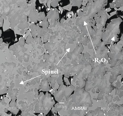
Figure 4. Electron micrograph of Monofrax K-3 showing (Mg,Fe)O•(AlCr)2O3 spinel phase and the R2O3 (Cr2O3-Al2O3 solid solution) phase. The R2O3 phase is present as chemically inhomogeneous cored grains. Credit: Monofrax
When in contact with melter glass, Monofrax fused cast chrome materials (K-3 and E) react with glass in an incongruent fashion (as in AZS in contact with soda-lime glass), leaving a byproduct at the glass–refractory interface. Magnesium and aluminum are the most soluble components of K-3, generally leaving the most insoluble component, Cr2O3, behind at the corrosion interface.
Monofrax K-3 in contact with waste glass simulant at the SRNL melter was characterized after service in 1984.14 Nickel and iron in the glass chemically behaved as a spinel former at the interface to create a nickel–iron–chrome spinel layer, somewhat metastable in the melter environment. This layer also inhibits further reaction at the interface by “passivating” corrosion rate at the glass contact. This chromium-rich spinel “skin” containing nickel is thermodynamically more stable than original phases containing higher alumina and magnesia. Spinel layer byproduct evolution path formation is as follows.
(Mg,Fe)O • (AlCr)2O3 → (Ni,Fe)O • (Cr, Fe, Al)2O3
Work by Jantzen15 at Savannah River Technology Center on the corrosion of K-3 by reducing and oxidizing feeds also found a highly insoluble protective layer of nickel spinel (Ni (Cr0.8 Fe0.2)2O4) at the K-3–glass interface.
Additional characterization of K-3 involved a research scale melter (RSM) from the Pacific Northwest National Laboratory (PNNL) that consisted of a small Monofrax K-3 cylindrical chamber with a 6-inch diameter melt pool. A test with this melter consisted of eleven weeks at temperatures of 1,050°C–1,150°C to observe the behavior of crystals precipitating out of the melt, which potentially can clog the outlet feeder to the holding cylinder.
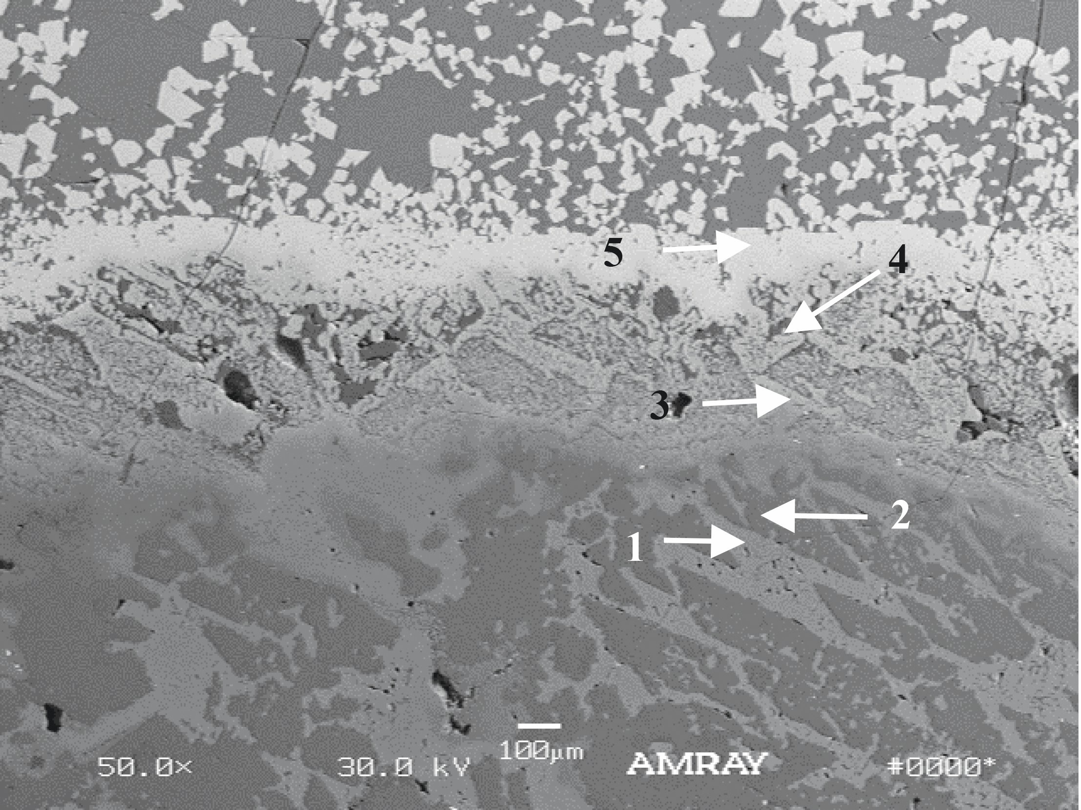
Figure 5. Scanning electron micrograph of the glass–K-3 interface at the bottom of the melter, revealing secondary phase formation at the reaction layer. Phases 1 and 2 are spinel and R2O3 solid solution, respectively. Phases 3, 4 and 5 are spinels with increasing nickel content and oxidized iron closer to the glass. Credit: Monofrax
Glass used in the test was a high nickel–iron–borosilicate glass (see Table 1) that resulted from a feed of the simulant liquid slurry mixed with glass formers (referred to as AZ-101 simulant). The scanning electron image in Figure 5 is from the glass–K-3 interface bottom of the melter, revealing secondary phase formation at the reaction layer. Phases 1 and 2 are spinel and R2O3 solid solution, respectively, with chemistries slightly altered from typical K-3 (Table 3).
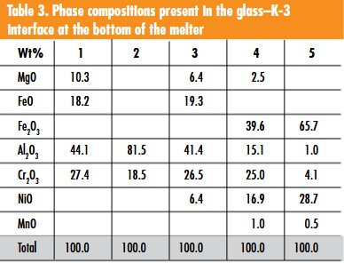
Moving closer to the glass–K-3 interface, the R2O3 phase dissociates by giving up its alumina portion. The spinel phase experiences oxidation with the FeO component going to Fe2O3, MgO, and FeO replaced by NiO, and alumina dissociating out to the glass as in the R2O3 phase (spinel phases 3, 4, and 5). The spinel stable phase at the glass–K-3 contact is a nickel spinel in the form: Ni0.9(Fe1.9Cr0.1Al0.5)2O4. Well-formed crystals in the waste glass simulant above the reaction layer are nickel spinel precipitates, which form in the glass and accumulate on the bottom.
The chart in Figure 6 tracks the chemical trend of magnesium, aluminum, and nickel from the glass–K-3 interface region towards the interior. This shows nickel replacing magnesium in the spinel phase, with a concomitant decrease in alumina as it migrates to the glass. The “normal” spinel composition for K-3 is found ~1 mm deep, keeping alteration of K-3 within a restricted zone at the glass–K-3 contact.
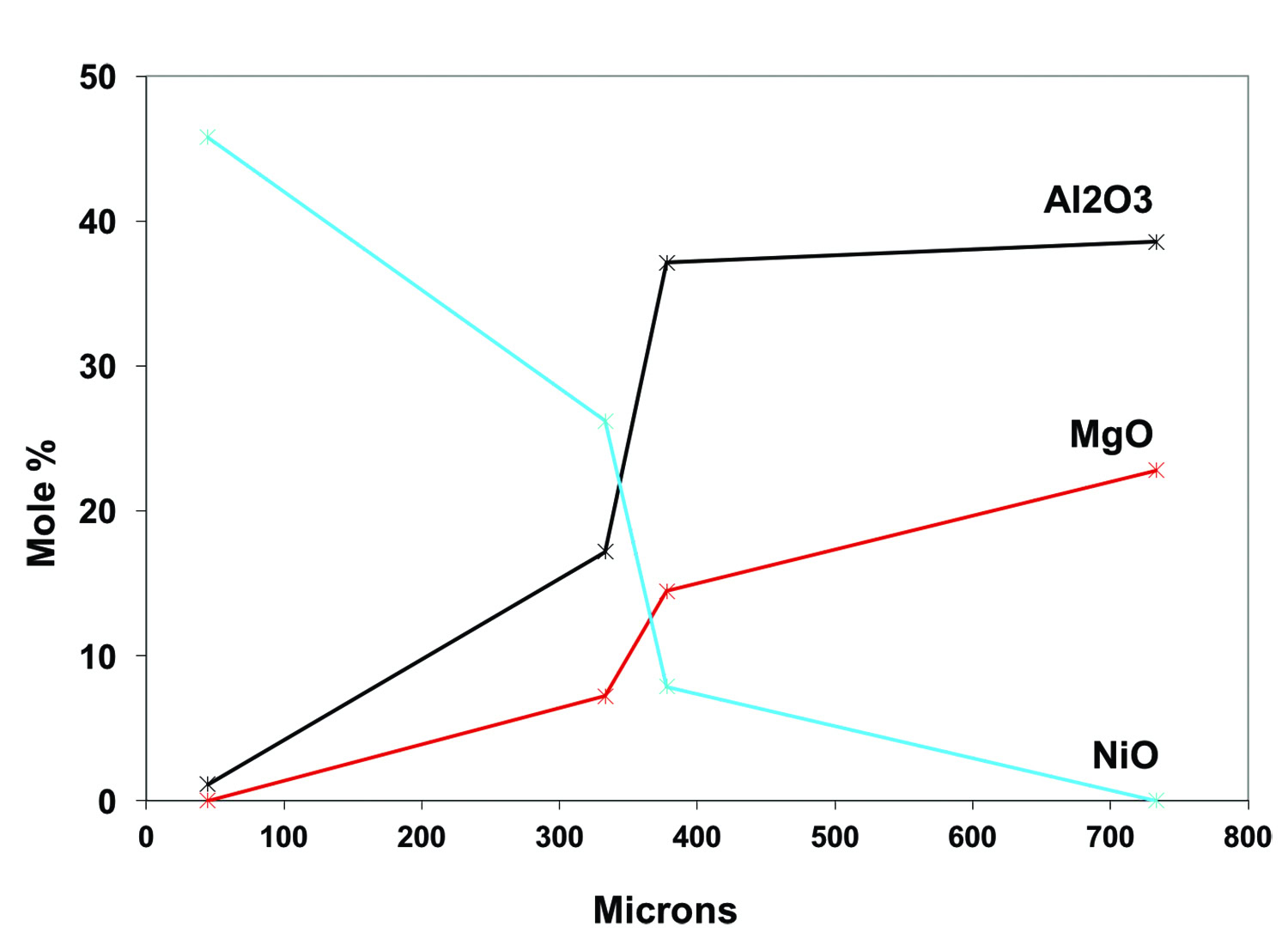
Figure 6. Spinel chemistry as a function of depth for magnesium, aluminum, and nickel oxides from the glass–K-3 interface region toward the interior (data from spinels in Table 3). Credit: Monofrax
The major phases of Monofrax K-3, spinel, and R2O3 are both solid solution phases and demonstrate the ability to adapt to transition metal levels in the waste glass. The consequence of this adaptability is formation of a secondary protective spinel layer reflecting the glass chemistry and oxidation state. In the PNNL melter, nickel replaces magnesium and reduced iron in the primary spinel of K-3, and ferric iron replaces alumina.
Future challenges of nuclear waste containment in glass
Operational challenges still exist in melters, specifically involving phase separations in the melter feed. Precipitation of a nepheline phase limits waste form performance by reducing chemical durability in the glass. Crystallization of transition metal spinels (Ni, Zn, Mn, Fe) (Fe,Cr)2O4 that accumulate at melter bottoms do not affect glass durability, but can plug outlet tubes, restricting flow to the stainless steel canisters for final disposal. The presence of molybdenum in many oxidation states within borosilicates can decrease the glass’s ability to prevent leaching in waste forms in longterm disposal sites.16
There is a surprising statistic concerning the number of nuclear reactors currently under construction in the world. The number under construction in Russia, India, the U.S., South Korea, United Arab Emirates, and Japan combined—approximately 30—matches the total under construction in China alone. China is the fastest-growing nuclear energy industry in the world with a 30% growth rate.17,18
Over the last forty years, nuclear applications have generated an estimated ~80,000 tons of spent nuclear fuel waste. As the number of operational plants increase, the amount of nuclear waste also will increase towards 2050. In particular, the amount of HLW is increasing because, while most of Europe and Asia reprocesses their spent fuel, the U.S. and Canada do not. Therefore, there is a growing need for acceptable and tested methods of nuclear waste storage, which vitrification can provide.
Acknowledgements
The author thanks the following reviewers of the manuscript for their comments and suggested modifications: William Eaton and Mark Hall, Pacific Northwest National Laboratory; Donna Post Guillen, Idaho National Laboratory; and Kai Xu, Wuhan University of Technology. The sample from the PNNL research scale melter was kindly provided by Albert Kruger, U.S. Department of Energy – Office of River Protection (Richland, Wash.).
Capsule summary
Containment
Disposal of nuclear waste is a complex problem—one solution is vitrification, in which glass is used as a containment medium to stabilize radioactive waste.
Design
As with industrial glass furnaces, refractory designs for nuclear waste vitrification melters call for a variety of refractories that corrode equivalently. Refractory linings in the glass furnace are a critical component of molten glass containment for glass articles.
Longevity
Nuclear applications have already generated thousands of tons of nuclear waste, and that amount will continue to increase. Although operational challenges still exist in melters, vitrification provides a proven method of nuclear waste storage.
Read more: “West Valley, NY case study“

Related Articles

Market Insights
Engineered ceramics support the past, present, and future of aerospace ambitions
Engineered ceramics play key roles in aerospace applications, from structural components to protective coatings that can withstand the high-temperature, reactive environments. Perhaps the earliest success of ceramics in aerospace applications was the use of yttria-stabilized zirconia (YSZ) as thermal barrier coatings (TBCs) on nickel-based superalloys for turbine engine applications. These…

Market Insights
Aerospace ceramics: Global markets to 2029
The global market for aerospace ceramics was valued at $5.3 billion in 2023 and is expected to grow at a compound annual growth rate (CAGR) of 8.0% to reach $8.2 billion by the end of 2029. According to the International Energy Agency, the aviation industry was responsible for 2.5% of…

Market Insights
Innovations in access and technology secure clean water around the world
Food, water, and shelter—the basic necessities of life—are scarce for millions of people around the world. Yet even when these resources are technically obtainable, they may not be available in a format that supports healthy living. Approximately 115 million people worldwide depend on untreated surface water for their daily needs,…