
Editor’s note—
“If you’re in the refractory business, you’re in the steel business.”—Conventional Wisdom.
A typical steel plant uses hundreds of types of refractories, each engineered for specific applications. Those responsible for specifying refractories must understand the diverse and demanding service environments, refractory product portfolio, and business drivers—and never compromise on safety to personnel, plant, and environment.
It is a daunting task. Vert has been there—as the refractory selection engineer and as the expert training others. Vert’s new book, Refractory Material Selection for Steelmaking, grew out of training materials he developed for new engineers to teach the fine art of refractory selection for steelmaking. Vert takes the reader/practitioner through his tried-and-true methods for establishing refractory selection goals. He reviews refractory types and available materials. He guides the reader through specific applications in the steel plant, and he pulls it all together with a chapter on refractory purchasing strategies.
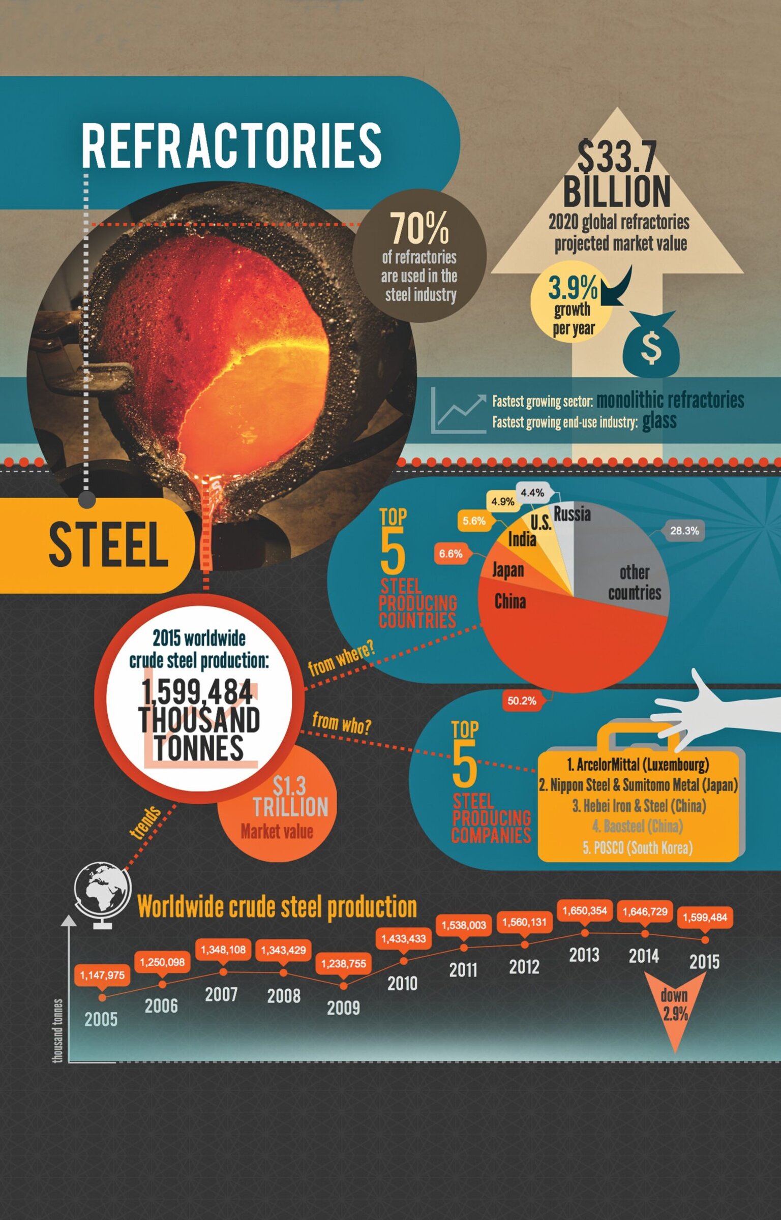
To illustrate the increasing market value of the refractories industry and some salient statistics on its biggest downstream market—the steel industry—see ACerS’ infographic at the bottom of this page. At a glance, see trends in the worldwide production of crude steel and learn about the top five steel-producing countries and companies.
Because the book was in production at the time this excerpt was prepared, it may vary slightly from the published book, but will match in its essentials.
The book will be published by Wiley–ACerS in May 2016.
Chapter 1
Editor’s note—A steel plant’s refractory selection team must balance safety, energy efficiency, environmental impact, steel quality, and cost. The “total cost of ownership” approach accounts for factors beyond the vendor invoice that impact the true cost of refractories selected.
Safety
Safety at any industrial facility is paramount and, in the case of making steel, is absolutely critical. The operation deals with molten liquids over 1,600°C in close proximity to people, which, therefore, requires a high amount of diligence. In refractory design, everything we do from a design point of view, we take into account safety.
Total cost of ownership
Total cost of ownership (TCO) is an analysis methodology that tries to capture all the costs associated with a refractory in use from purchase to disposal, including the impact to the process itself. From a basic point of view, it starts with what is the total cost/tonne of refractory, including all costs (refractory, process, etc.) divided by the total tonnage produced.
An example of a TCO for the BOF furnace, which will be used to demonstrate how these calculations are done and the actual impact, is shown as follows.
There are six major areas:
- Actual main refractory purchase;
- Logistical costs;
- Installation and demolition costs;
- Refractory maintenance costs;
- Refractory energy costs; and
- Operational impact.
Refractory material purchase
The first and most obvious cost and the one that draws the most attention is the purchase cost itself—this can represent “sticker shock” in some cases, whereby a BOF lining can be over $1 million in a one-time purchase. Therefore, it will always draw attention of those in the purchasing process as an area of opportunity to drive down costs.
This purchase cost is then broken down by the following equation:
Total price of the refractories ($) = weight of material needed (kg) × price of the material ($/kg)
The weight of the material needed is a function of the design of the vessel, and the only way to change this is to make the lining thinner in areas in which it has low wear without risking undermining other areas, as presented in Figure 1.15.
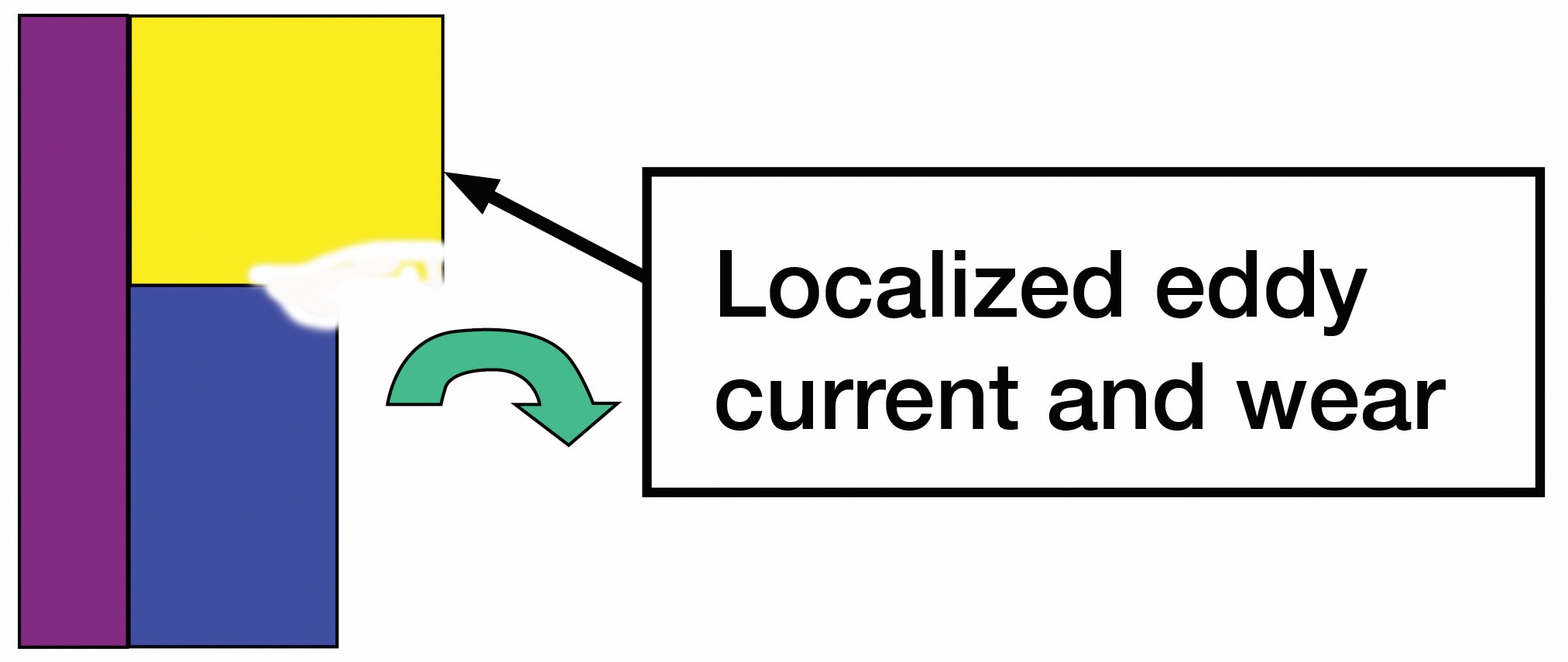
Fig. 1.15. Localized wear caused by varying material thickness. Credit: Wiley; Vert
The price of the material is the other variable, and this is influenced by the material selected (e.g., fused grain, material purity, and supplier). Note that the materials must always be chosen first to match the TMC (thermal–mechanical–chemical) design analysis (discussed in Chapter 2) and not to have a lower price per kg for low price purposes only! This will always be a key pressure point with people who purchase the refractories with a mindset of it being a commodity rather than an engineered material. (Which of course we know it is not!)
There is always a tradeoff between performance and cost. See Figure 1.16 as an example. As the purity increases, the price per kg increases exponentially. This is true for most components, i.e., MgO, graphite, etc.
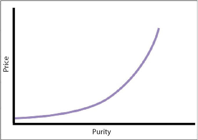
Fig. 1.16. Effect of material purity on price. Credit: Wiley; Vert
The final part of this equation is, of course, the cost/tonne of refractories following the equation:
Cost/tonne = cost of the refractories ($)/steel produced through the campaign (tonnes)Steel produced (tonnes) = number of heats made × average heat size (tonnes)
Therefore, in order to reduce the cost/tonne, there are only three options:
- Reduce the cost of the refractories;
- Increase the campaign life or number of heats on the production unit (longer life)—(less downtime); and
- Increase the average heat size (usually restricted by design of vessel or cranes).
In case of design, all three options have been and continue to be utilized:
- Example: Redesign the materials in a BOF in low-wear areas or in the ladle slagline (lower purity MgO, lower purity graphite, etc.), which maintains heat life and heat size but lowers the initial cost.
- Example: Redesign an EAF bottom to go from 500 heats to 1,200 heats through a change in construction with same brick sizing and costs, but longer life leading to a lower cost/tonne.
- Example: Redesign a ladle to increase average heat size—thinner safety linings, higher ladle shell—same life of the ladle, same refractory cost—but lower cost/tonne.
All options are available, although some are more restricted based on steel plant design itself.
Chapter 2
Editor’s note—“Thermal–Mechanical–Chemical Analysis” provides a method to systematically specify refractory performance.
TMC analysis overview
The first thing you want to think about is what material and installation method will solve the problem. This will not be discussed until Chapters 3 and 4 on purpose—because the key to refractory selection is #1—“What is the problem?” What is the wear you are trying to solve once the goals have been determined in Chapter 1?
For all existing refractory problems or any new installations that are being analyzed, full TMC analyses (Table 2.1) are the first steps to be done. These and their combinations are the wear mechanisms of refractories, and their analyses are essentially an examination of the process under which the refractories are submitted.
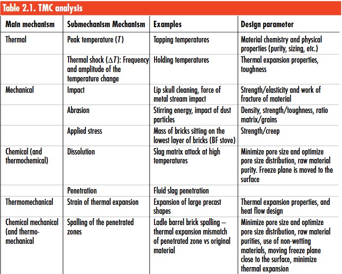
Credit: Data from Refractory Material Selection for Steelmaking; table formatted by ACerS
A key to this analysis is also to analyze from a refractory perspective. Refractory specialists are used for this, because metallurgists usually understand the steelmaking process but do not understand refractory properties and, therefore, cannot appreciate the effect of the former on the latter.
The TMC analysis is then compared against the refractory properties in order to select the proper material. Note that it is important to comment that the current state of supplier data sheets is useless, giving only the information that won’t help you. Supplier data sheets are weak, because, firstly, they give overall chemistry, which is misleading (and usually any key components will be left off), and, secondly, most of the important tests, such as slag testing, have no standard. An ideal situation, as a customer perspective, we would like to know the minerals used, their placement in the particle size distribution, and the engineering properties, such as hot modulus of rupture at temperature, work of fracture, and thermal expansion curves, not just point values. Based on this discussion, it is critical for the end user to take an active role in the refractory material selection process—but more about this in Chapter 5!
In closing, the age-old adage, “What is the problem?” is the key to starting in refractory material selection.
Editor’s note—Phase diagrams are essential tools for the refractory engineer. Vert presents industrially important phase diagrams and walks the reader through correct interpretation. The chapter addresses fundamental wear mechanisms and consequent engineering decisions. These concepts tie together by coming back to TMC analysis.
The last section of this chapter deals with three key topics:
- Interactions of TMC analysis;
- Saturday night designing (see sidebar); and
- Rubble pile analysis (see sidebar).
The review of all three topics will pull everything together and essentially leave readers at the point that they can understand what we stated in the first section—the key to refractory selection is #1—“What is the problem?” What is the wear you are trying to solve once the goals have been determined in Chapter 1?
Interactions of TMC analysis
For all existing refractory problems or any new installations that are being designed, a full TMC analysis is the first step to be done, and we have reviewed the key components of the first section’s charts with details on thermal, mechanical, and chemical key wear mechanisms. Let us now review the interactions between these phenomena as shown in Figure 2.53.
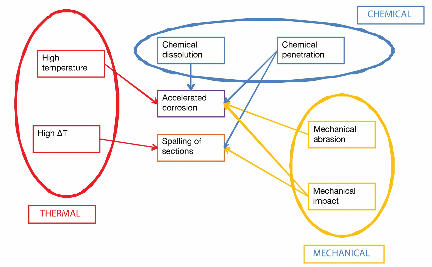
Figure 2.53. Interactions of TMC analysis. Credit: Wiley; Vert
In reality, this diagram, although messy, is much more reflective of what actually happens in service, with multiple interactions and never one single wear mechanism. A good example would be a ladle slide gate:
• High abrasion environment with sliding refractory surfaces;
• High thermal shock from pouring of steel to shut off; and
• High chemical attack from calcium vapour for calcium steels.
So, if we are to design for abrasion and use very hard and strong materials, then we will fail quickly from thermal shock, because we need soft flexible materials. If we design strictly for thermal shock, than the abrasion will wear the plates quickly. If we try to put very dense material with tight pore size for corrosion or use a magnesia-type material, the plate will fail because of thermal shock within a heat or two! There is no perfect answer, and the process variability in a shop from heat to heat and day to day adds additional challenges.
So what do we do? We compromise, we balance—I like to compare it to the fairy tale “Goldilocks and the Three Bears”—it is a balanced approach.
Chapter 3
Editor’s note—Phase diagrams and fundamental materials science concepts explain and demonstrate wear mechanisms for major steelmaking refractory compositions.
Magnesia (MgO) overview
Magnesia is probably the key ingredient in steelmaking refractories in the world today, and an understanding of its key characteristics is critical to improvements and cost/value for any steel shop.
It has a high melting point of ~2,800°C in its most pure form and is manufactured from either minerals in the ground or some type of seawater.
Importance of magnesia purity
Note that the key components of MgO are
1. MgO concentration;
2. Crystal size;
3. Impurities;
4. Sintered/fused ratio; and
5. MgO concentration.
Why do we care?
– Performance, purity, and price are all related;
– We want to be working in the “sweet spot” between purity and price, as shown in Figure 3.6; and
– Goal in life (as a refractory engineer): To find the sweet spot!
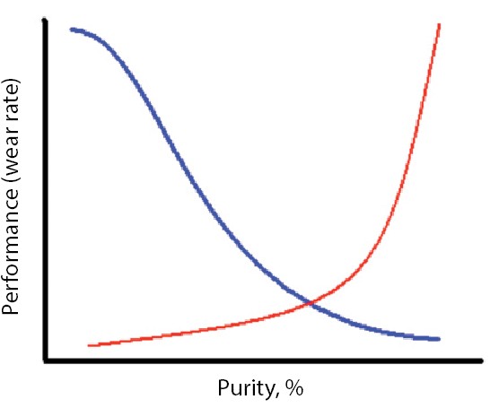
Fig. 3.6. Relationship of performance and raw material purity. The ideal is to work in the “sweet spot.” Credit: Wiley; Vert
Impurities
There are three important things to check with impurities—the total amount, the level of B2O3, and the C/S (or lime/silica ratio). Total amount of impurity compounds includes: Al2O3, CaO, SiO2, B2O3, and FeO, Fe2O3
As the total number of impurities increases, the crystal size decreases, and, then, the wear rate increases, as shown in Figure 3.12.
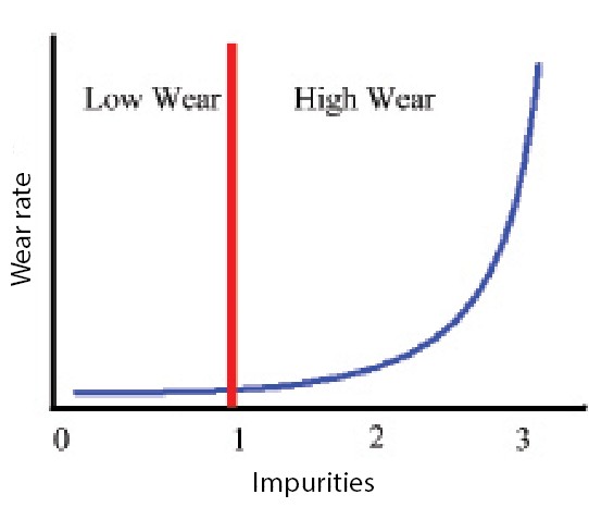
Fig. 3.12. Relationship between wear rate and impurities for MgO grains. Numbers are not accurate—but the relationship is similar and depends on the application. Credit: Wiley; Vert
Percent B2O3
At steelmaking temperatures (1,600°C), even with small amounts of B2O3 (less than 0.001%), a liquid will form at 1,155°C as shown in the phase diagram in Figure 3.13. It forms along the grain boundaries, as shown in Figure 3.14. So, even if you have >98% MgO, it doesn’t matter. The amazing crystal will pop out because of the weakness of the small amount of liquid phase forming.
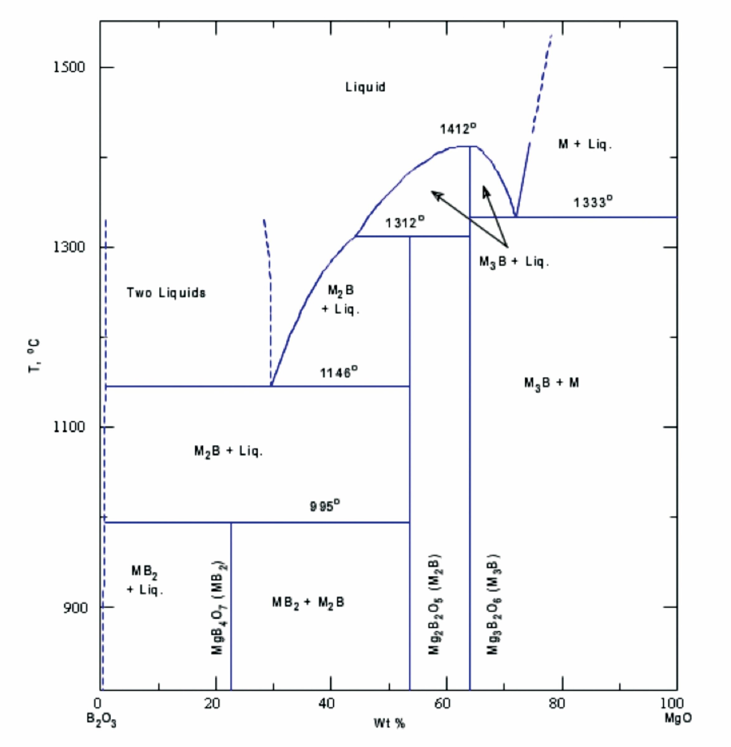
Fig. 3.13. B2O3 and MgO binary phase diagram. Credit: Wiley; Vert
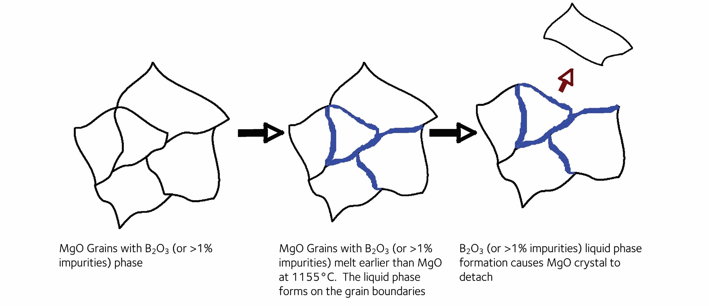
Fig. 3.14. Liquid formation in MgO grain boundaries with the presence of B2O3. Credit: Wiley; Vert
Chapter 4
Editor’s note—Refractory selection requires knowledge of refractory products and their properties as well as proper installation methods. The refractory portfolio includes brick, monolothics, castables, specialty refractories, and installation hardware, which combine in a complex, highly engineered system for safe and economic steel production.
Refractory dryout and anchoring overview
Why is the choice of installation method so important to the selection of refractories? Why do we focus on it so much? Material properties and lining performance can be affected by installation and manufacturing of the products.
I like to compare it to Mark Twain saying: “Golf is a good walk spoiled.” Well, refractory installation is good raw materials possibly spoiled. You can’t make the raw materials better, but you can devastate properties with poor installation. In order to discuss installation, we need a basic overview of refractory manufacturing.
Refractory making is at first a series of crushing, sieving, and mixing of the different raw materials. Although simple, the refractory supplier process should be controlled to fit the chemical formulation and also the grain size distribution. If the grain size distribution is not correct, the physical properties, such as a higher porosity/permeability, and lower mechanical strengths, will be strongly affected.
The rest of the making process depends on the type of refractory:
- Brick are required to be made into a designated shape and must have a curing treatment to get enough mechanical strength for handling and transportation (unfired brick). If refractory is fired, brick go through a tunnel shaft or furnace for typically 24 hours at 1,200°C to as high as 1,800°C. Carbon-free refractory is fired in air, but resin-bonded pieces, such as slide gates, are fired in coke-filled boxes and in oxygen-deficient environments. By firing, the aggregates sinter together, making a ceramic bond.
- For monolithic refractory, such as castable, mortar, and plastics, the shaping method will depend on the installation location, skills needed to install, and local site issues, as shown in Table 4.1. This means that refractory properties rely on the installation and “setting” rules (water addition, mixing, casting time, drying) so that hydraulic bond develops with the hydration of the high-Al2O3 cement. Rheological behaviour of the mixed castable is also of utmost importance: It is controlled by the presence of some percentage of active components (accelerators/retarders and ultrafine particles, the recipe of which makes the core of the supplierknow-how). If not correct or in case of unusual impurities brought by other raw materials, rheology and final properties of castables will be strongly affected.
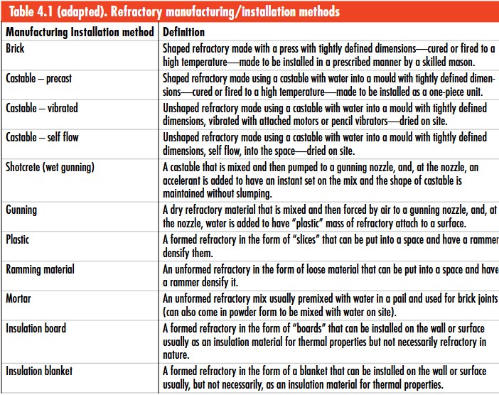
Credit: Data from Refractory Material Selection for Steelmaking; table formatted by ACerS
Figure 4.3 shows a comparison of three key monolithic refractory installation methods.
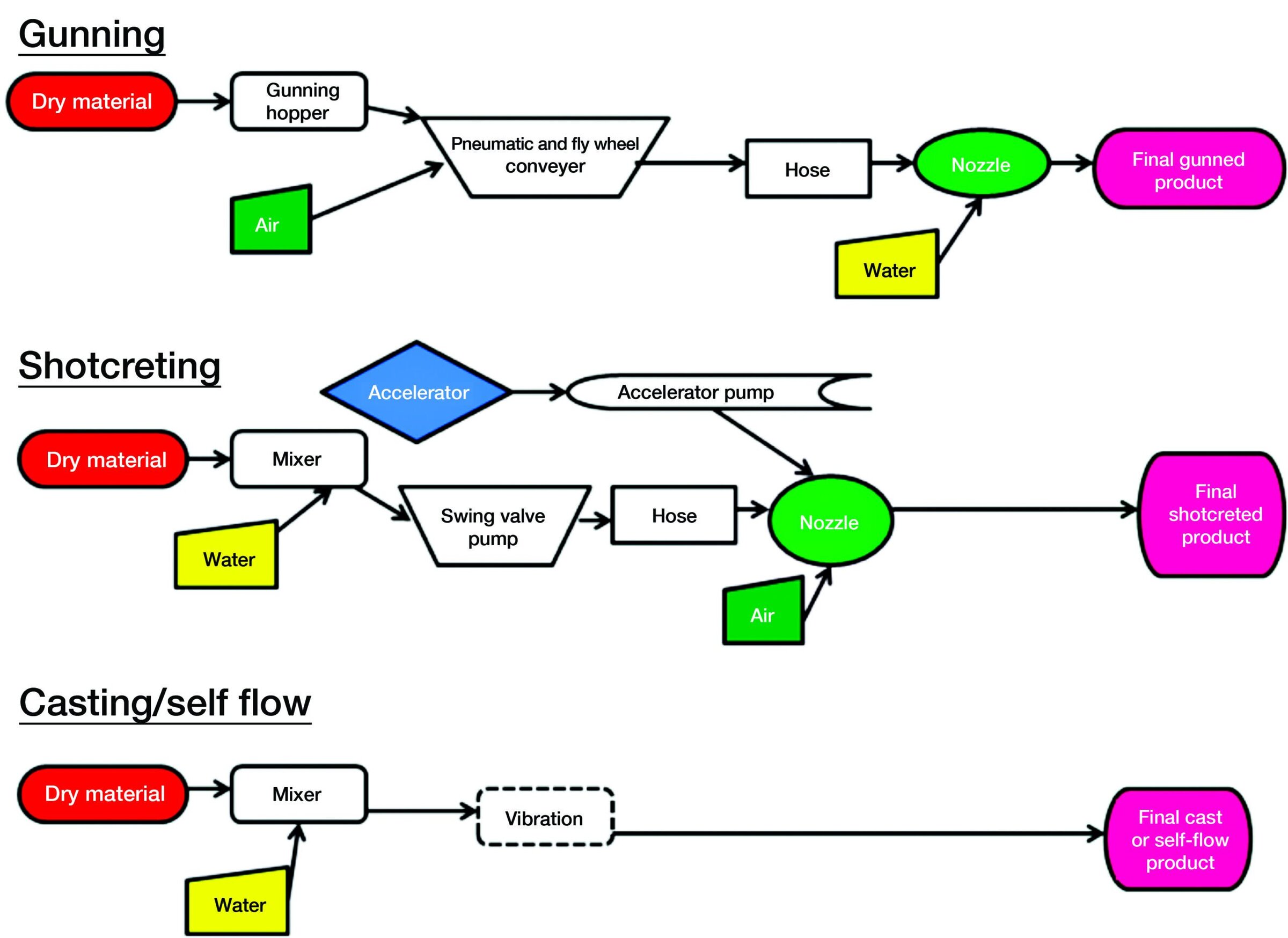
Fig. 4.3. Monolithic installation schematics. Credit: Wiley; Vert
Chapter 11
Editor’s note—Final refractory selection combines technical and operations requirements with business considerations. Employing the analysis methods introduced throughout the book, especially the total cost of ownership, the refractory-selecting engineer will be well equipped to make a final recommendation to the purchasing team.
Purchasing strategies
Selecting and purchasing refractories is a very interesting part of the total business. Recall that in Chapter 1.6 we talked about TCO—Total Cost of Ownership. This is an analysis methodology that tries to capture all the costs associated with a refractory in use from purchase to disposal, including the impact to the process itself—i.e., life, productivity, yield, quality, etc.
It should take into account all components of the buy to make the most rational, logical decision on an individual buy basis.
However, what if there is a “preferred” supplier who is not the one chosen that is requested to be used? What if the vendor selected is on the corporate “black list”? What if choosing one supplier will gain a big savings at a sister plant?
There are other key questions as well. Should we buy the refractory by the pound? By the piece? By the cost per tonne of steel produced, or by some other method? Also, should purchases be made on consignment (invoiced when used) or on a ship-and-bill basis (invoiced when shipped by the supplier)?
All of these are key questions that the refractory selector must also take into account and which will be discussed here. Another important thing that must be remembered is that the refractory selector does not normally have the final decision—this is done in combination with the operators, purchasing people, etc., as shown in Figure 11.1.
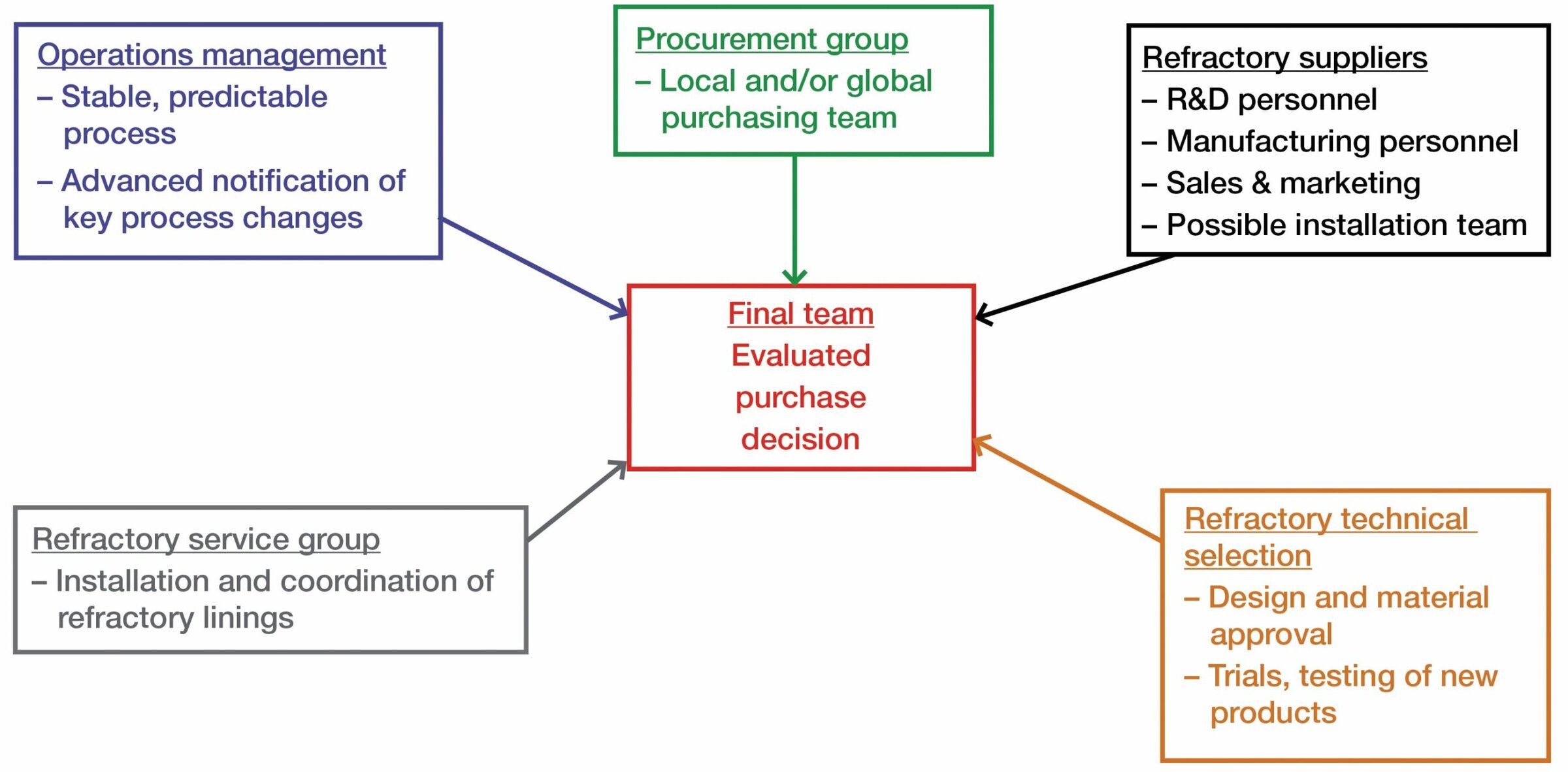
Fig. 11.1. Key input to refractory purchase decisions. Credit: Wiley; Vert
Note: Each of these groups has a role to play, However, it should be noted that the final decision should reside with the operations/process managers, because they are responsible for safety, production, and cost within the plant—all others have key input, but the production/process managers are ultimately accountable.
Also, we must remember that selecting refractories is a highly complex and highly technical decision—we are selecting engineered ceramics, not everyday industrial commodities!
This is crucial and not just a statement to keep nontechnical decision makers out of the final decision, but instead to ensure the lowest TCO decision is correct. For example, it once took one plant 12 months of trials to design and select the proper mortar for installing ladle argon plugs and nozzles. It had to have the right chemistry, the right consistency, and it had to bond quickly for installation but have some friability for removal. This took multiple trials with different bonding systems and mineralogy to get the right mix. Many would think an 80%-alumina mortar was just a commodity material and the lowest price for a 25-kg pail would be the deciding factor, but this would be totally wrong.
Does this mean that there are not some refractories that are not commodities? No! Does this mean that we can’t commoditize the refractories to help our purchasing agents negotiate? No!
But it does mean that the right technical work must be done first with the team to get the right product!
Tips, tricks, and steel plant wisdom
“Saturday night” designing
The statement of “Saturday night” designing is a simple one and basically tries to focus on keeping in mind worst case scenarios and ensuring full risk is built in.
If you are designing an application based on average temperatures, average ΔT, average chemistries, etc., then it will be prone to premature failure. The worst case scenario for a steel plant usually happens on Saturday night when there is little supervision. The operators are pressed to make steel when things like “hot heats” with tap temperatures of 1,700°C or superheated slags tend to take place.
Saturday night designing needs to be taken into account—a wise old refractory guru once said, “If you design for Saturday night, the rest of the week will be fine!”
Rubble pile analysis
Refractory selectors will never be able to get to optimum designs/costs unless they are willing to get dirty!
To truly understand wear mechanisms, you must be willing to wade into the rubble piles in the steel shop. A laser analysis of a steel ladle slagline thickness will tell you a wear rate, but if you get into the ladle, you will find so much more. If you dig a brick or two out by jackhammer, pry bar, or brick hammer, you will possibly notice:
- Softness of the brick from oxidation of the bond that you can feel when you dig it;
- White back face from oxidation of gases coming up the back side during preheat and/or during the process cycling;
- Vertical, horizontal cracks—How many? Where? How deep from hot face? Corners vs whole face?;
- Slag/steel penetration of the joints;
- Depth of penetration of the slag (thin/thick); and
- Dissolution of the matrix or the grains or both.
All of this will tell you 10 times more about the wear mechanism than any data scan or computer analysis of the process.
It also gives you the keys to then design around wear mechanisms!
Steelmaking glossary Adapted from American Iron and Steel Institute www.steel.org
Basic oxygen furnace (BOF)
A pear-shaped furnace, lined with refractory brick, that refines molten iron from the blast furnace and scrap into steel. Up to 30% of the charge into the BOF can be scrap, with hot metal accounting for the rest. Scrap is dumped into the furnace vessel, followed by hot metal from the blast furnace. A lance is lowered from above, through which blows a high-pressure stream of oxygen to cause chemical reactions that separate impurities as fumes or slag. Once refined, the liquid steel and slag are poured into separate containers.
Blast furnace (BF)
A towering cylinder lined with refractory brick to smelt iron from iron ore. The name refers to the “blast” of hot air and gases forced up through the iron ore, coke, and limestone that load the furnace.
Electric arc furnace (EAF)
A steelmaking furnace where scrap is generally 100% of the charge. Heat is supplied from electricity that arcs from the graphite electrodes to the metal bath. Furnaces may be either alternating current or direct current. Direct current units consume less energy and fewer electrodes, but they are more expensive.
Continuous caster (CC)
Steel from the BOF or electric furnace is poured into a tundish (a shallow vessel that looks like a bathtub) atop a continuous caster. As steel flows from the tundish down into the water-cooled copper mold of the caster, it solidifies into a ribbon of red-hot steel. At the bottom of the caster, torches cut the continuously flowing steel to form slabs or blooms.
Ladle
A “bucket” lined with refractory brick, used to transport molten steel from process to process in a steel plant.
Tundish
The shallow refractory-lined basin on top of the continuous caster. It receives liquid steel from the ladle, prior to the cast, allowing the operator to precisely regulate flow of metal into the mold.
Created by April Gocha using Piktochart.com. Sources: ReportsnReports, “Global and China Refractory Material Industry Report, 2014–2016”; MarketsandMarkets, “Refractories Market—Trends & Forecasts to 2020”; Visiongain, “Steel Market Forecast 2015–2025: Future Opportunities for Leading Companies”; World Steel Association statistics, available at worldsteel.org.


Related Articles

Market Insights
The evolving discipline of demand forecasting can improve competitiveness and control costs
What does the future hold? It is a question that everyone has contemplated at one time or another, and a mystery that has obsessed writers, mystics, philosophers, clerics, astrologers, and others for centuries. For businesses, the question is more than philosophical. Discovering clues to what is next is essential to…

Bulletin Features
Sustainable ceramics production: Environmental considerations in tile manufacturing
Ceramics are often regarded as a sustainable material choice thanks to their high durability and chemical stability, which enable a long service life. But ceramics come with environmental baggage in other areas, such as raw material sourcing, processing, and disposal. The specifics of this baggage are unique to each ceramic…

Market Insights
Financing the responsible supply of energy transition minerals for sustainable development
As the world transitions to sustainable development and the achievement of net-zero emissions by 2050, the demand for specific minerals and metals, such as lithium, nickel, and copper, is surging. These minerals are crucial for the development of batteries, solar panels, and electric vehicles, and therefore are central to clean…