
Deep in the heart of your car’s exhaust system—withstanding temperatures of more than 1,800 degrees Fahrenheit and staying tough over hundreds of thousands of miles of bumpy roads—a highly engineered ceramic material is an important part of helping to prevent harmful emissions from escaping into the air you breathe.
By keeping the air cleaner, these same ceramic products help save as many as 160,000 lives each year and help to prevent just as many cases of heart disease and asthma.1
From 1975 through today, light and heavy-duty vehicle emissions dropped by an astounding 99%. Ceramic-based mobile emissions control products prevented more than 4 billion tons of hydrocarbons, 4 billion tons of nitrogen oxides (NOx), and 40 billion tons of carbon monoxide from entering the atmosphere.
The clean-air movement brought economic benefits as well. Emissions-related technologies represent about $37 billion in annual economic activity, with a significant portion of the industry involving ceramic-based components.2
Innovations in ceramics will continue to be needed for at least the next couple of decades. Consumers throughout the world, not only in areas with untreated mobile pollution sources, are demanding better air quality. Areas of focus that continue to drive ceramic innovations include
- Ensuring that real-world emissions are as low as emissions on the certification test;
- Gaseous emission limits reducing, particularly NOx emissions, while supporting the reduction of greenhouse gases; and
- Reducing the last remaining bursts of gaseous and particulate emissions from internal combustions engines, the emissions that occur during the first minute or two of vehicle operation—an event that can happen several times during a drive with hybrid vehicles.
A growing dirty problem
By the late-1940s, industrial activity in the United States had grown for nearly a century. Little attention was paid to the consequences of smoke and pollutants from coal-burning factories. Suburbs were growing. More and more families could afford cars. With city traffic crowding new highways, unprecedented levels of harmful chemicals flowed into the air, especially in major population centers—both in the U.S. and in other developed countries.
The health hazards associated with poor air quality came into stark global view in London in late 1952, when airborne pollutants, mostly arising from the use of coal, mixed with fog to form a thick blanket of smog over the city. Historical accounts vary on the details, but most agree between 4,000 and 6,000 people died over the course of five days from the choking effects of the Great Smog.3,4
The following year, New York City was covered with a toxic mix of sulfur dioxide and carbon monoxide that blanketed the city. During one week, according to reports, as many as 260 deaths were attributed to the smog. More deadly smog crises would hit both New York and London again over the following decades.5
With the public health effects of air pollution now beyond dispute, the U.S. began its first attempt to legislate a solution with the Air Pollution Control Act of 1955, which focused on research and information, leaving the states to devise ways to deal with polluters. A few states, notably California, had a plan to combat the issue.
The U.S. government made several more attempts to regulate sources of air pollution. However, the Clean Air Act of 1963, the Motor Vehicle Air Pollution Control Act of 1965, and the Air Quality Act of 1967 all lacked the teeth to make a difference in the deadly problem.
But in 1970, sweeping new federal regulations required clean-air compliance from every segment of industry. The new Environmental Protection Agency (EPA) was formed with the mandate to enforce the regulations.
The Clean Air Act of 1970 established air-quality standards that strictly limited levels of six pollutants that threatened public health: sulfur dioxide, nitrogen dioxide, particulate matter, carbon monoxide, ozone, and lead.6 (See “Clean Air Act of 1970”)
For automakers, the government’s marching orders were clear: design vehicles that could run on unleaded gasoline and incorporate a new device—the catalytic converter—to reduce carbon monoxide and hydrocarbons by 90% from car exhaust. By 1975, all American-made vehicles were required to meet the new emissions requirements—no exceptions. European countries implemented similar regulations in 1992.
A technical challenge, a business opportunity
Around the same time in 1970, Corning was bringing its materials science expertise to General Motors with the idea of a lightweight, chemically strengthened glass windshield made on its new fusion-draw process. GM had little interest in Corning’s windshield glass, as the recently developed Pilkington’s float process was more economical. While at GM, Corning president Tom MacAvoy showed GM president Ed Cole a sample of a unique glass-ceramic material called CERCOR®. Light and highly resistant to heat, Corning envisioned marketing CERCOR material as a heat exchanger for gas turbine engines. Cole told MacAvoy that the industry was moving away from turbine engines, but he liked Corning’s ingenuity. He urged the company to investigate the substrate opportunity for catalytic convertors.
GM and other automakers had settled on internal combustion engines and the catalytic converter, first patented by French-born mechanical engineer Eugene Houdry in 1955, as the solution for reducing harmful engine emissions. The converter required unleaded gasoline and a durable substrate with low resistance to flow that also provided a lot of surface area, allowing the exhaust to pass over the platinum group catalysts supported on high-surface-area gamma-alumina.
Many capable people were trying to solve the problem, including those at GM, 3M, W.R. Grace, Engelhard, Johnson Matthey, and more. But as of 1970, no clear winning substrate technology emerged. Corning chief technology officer Bill Armistead responded to MacAvoy’s challenge by launching an internal emissions control (EMCON) project and directed significant funding into its R&D efforts.
Advanced glass was Corning’s best-known specialty, but the company’s skill in ceramics dated back to the late 19th century, when engineers designed and created durable ceramic crucibles for melting glass. In 1920, the company formed a ceramics research group and soon began making ceramic refractory bricks with extreme chemical durability. The bricks were ideal for lining the continuously operating melting tanks used to mass-produce light bulbs as well as one of the company’s newest products: PYREX kitchen ware.
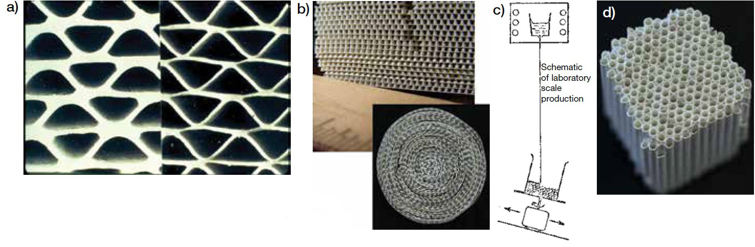
Figure 1. Numerous pathways to fabricating porous ceramic substrates were tried before settling on extruded honeycombs. (a) Alternate layers of flat and crimped paper infused with glass-ceramic (CERCOR material); (b) layers of cordierite glass-ceramic sheets with small “nubbins” to increase the surface area and permit exhaust flow; (c) open, layered structure similar to ribbon candy formed by buckling a hot glass stream and later ceraming the part; and (d) glass tubing fused together, then ceramed, looking like a packet of hollow cigarettes. Credit: Beall and Cutler
Corning approached the emissions-control project by researching a wide variety of designs and materials. Under consideration, for example, were (Figure 1)
- Alternate layers of flat and crimped paper infused with CERCOR glass-ceramic material;
- Layers of cordierite glass-ceramic sheets with small “nubbins” to increase the surface area and permit exhaust flow;
- An open, layered structure, not unlike ribbon candy, formed by buckling a hot glass stream and later ceraming (i.e., heat treating to induce crystallization of the glass) the part; and
- Glass tubing fused together, then ceramed, looking like a packet of hollow cigarettes.
Competitors were testing potential solutions just as wide-ranging.
- American Lava Corporation (a subsidiary of 3M) developed a way to alternate layers of flat and corrugated ceramic-impregnated paper, which was then slowly fired. The design used zircon-mullite and cordierite-mullite compositions.
- W.R. Grace devised a ceramic powder-filled plasticized polyolefin sheet with ribs. The sheet was rolled and heat-sealed, providing parallel airflow paths. The polymers were burned off to form the final product.
- General Motors’ in-house team used a packed bed of catalyst-coated ceramic beads rather than a structured ceramic.
Technically, several of the designs worked. But the question of manufacturing—specifically, how to produce millions of substrates per year, at a low cost—was most challenging.
A breakthrough solution
The tide turned in July of 1971 when two young Corning scientists—Ed Bush and Rod Bagley—were in a meeting with a colleague at the company’s research campus, Sullivan Park. Bagley described an idea he had mulled over—using extrusion to make a cellular substrate structure.
He sketched his idea on blackboard. The original design had offset slots in both sides, but it was not clear to the others how it would work. To clarify the concept, he ran to the mason’s shop and grabbed a soft refractory brick and used a diamond saw to make a 3D model, further demonstrating the concept.
The first practical embodiment was a custom-made brass prototype die about 25 mm in diameter, which produced parts with 50 cells per square inch and cellular walls roughly 0.5 mm thick (Figure 2). Bagley extruded alumina through the brass die to test the idea.
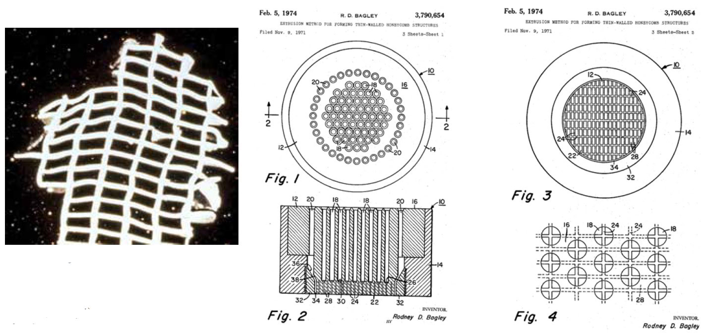
Figure 2. Results from the first extrusion of cellular ceramic (left), and drawings from the patented idea filed in November 1971. First tested in July and first scaled in October 1971. Credit: Beall and Cutler
Meanwhile, scientist Irwin Lachman was developing a cordierite-mullite composition with a remarkably low coefficient of thermal expansion (CTE)—a material that could remain stable and functional despite the repeated extreme heating and cooling experienced within a car’s powertrain system. Lachman worked with Ron Lewis to improve the material. The resulting synthetic cordierite not only had very high temperature capabilities (Tm >1,400°C) but also great thermal shock resistance.
The first successful 4.66-inch (118 mm) diameter extrusion of cordierite was in 1971 (this diameter is still a common diameter for automotive exhaust components). Corning branded the new ceramic substrate as Celcor® and received its first order—from Ford Motor Company—by the end of 1971.
It worked so well that Corning—even as it was financially challenged in the increasingly global color TV glass market—shelved other potential substrate solutions and quickly invested $25 million into a new environmental factory in Erwin, N.Y. This Corning factory depreciated over five years, as car companies claimed they would improve their engines so that catalytic convertors would not be needed in the future. Instead, the market continued to grow, and the factory is still operational today.
What’s special about cordierite?
Naturally occurring cordierite is a mineral compound containing magnesium, iron, aluminum, and silicon. It is found, among other places, near veins of tin in the mines of Southern England. It draws its name from French geologist Louis Cordier, who included the mineral in a much-celebrated geological gallery at the National Museum of Natural History in Paris in 1813.
The synthetic version of cordierite that Corning scientists created included no iron and contained magnesium, aluminum, and silicon (Mg2Al4Si5O18), creating a new material for emissions-control products.
Irwin Lachman was working with cordierite for other applications at the time of Bagley’s invention of the die. Lachman considered cordierite an attractive choice of material for several reasons.
First, the application required a very high level of thermal shock resistance, and cordierite was known to have a very low CTE. Second, cordierite had good high-temperature stability and therefore could survive even the highest temperatures that would be encountered in the application, and it also had good chemical stability in the environment that would be encountered in the vehicle exhaust. Third, cordierite could be synthesized from relatively inexpensive and commonly available batch materials such as talc (Mg3Si4O10(OH)2), kaolinite clay (Al2Si2O5(OH)4), and gibbsite (Al(OH)3) or corundum (Al2O3).
Lachman combined these raw materials along with a methyl cellulose binder and water to produce a plastic mass with a putty-like consistency, which could be pushed easily through Bagley’s extrusion die to produce the honeycomb structure. The extruded honeycomb parts were then dried to remove the water and fired to a high temperature, allowing the raw materials to react together to form the cordierite phase.
Lachman found that, after firing, the raw materials converted to over 95% cordierite phase. The fired ceramic honeycomb was porous, containing about 30 vol% of porosity in the walls. The presence of the porosity proved to be advantageous compared to a dense ceramic because the pores in the ceramic walls allowed the washcoat containing the catalyst to be slip casted onto the walls. The porosity also fortuitously decreased the heat capacity of the honeycomb relative to a dense ceramic, allowing it to heat up faster in use to the temperature where the catalyst became active.
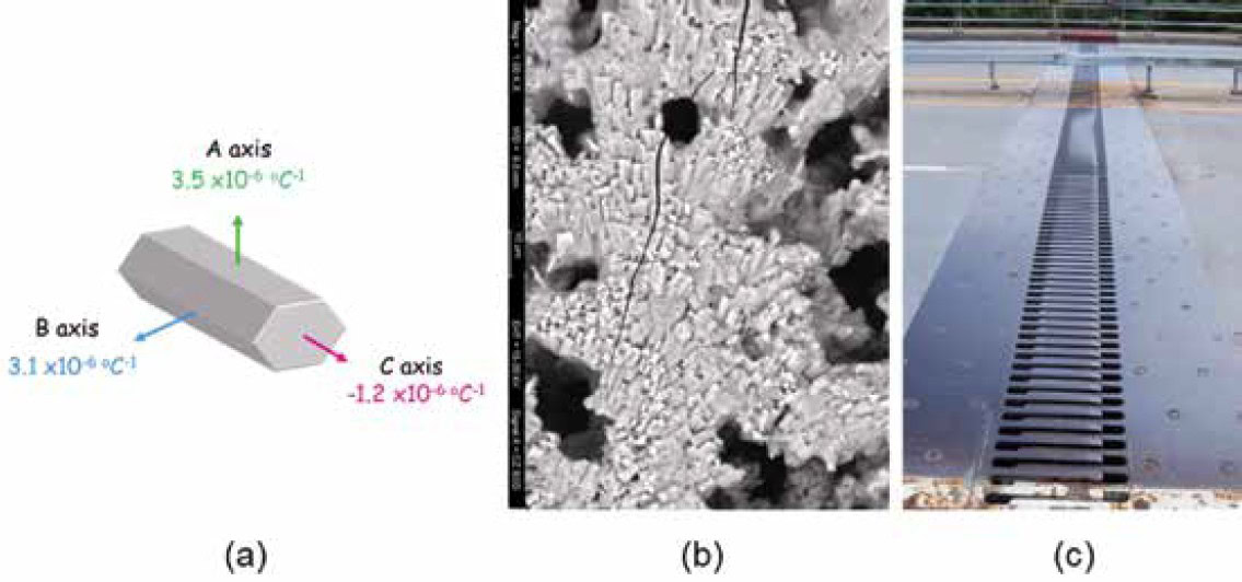
Figure 3. (a) Schematic of orthorhombic cordierite crystallite showing anisotropy in thermal expansion. (b) SEM micrograph of the web surface of a cordierite honeycomb showing orientation of individual cordierite crystallites and microcracks that act as engineered expansion joints. Dark areas are pores. Width of view is approximately 80 µm. (c) Expansion joint in a bridge, which allows for thermal expansion of the bridge components, but the length of the bridge itself remains constant. Credit: Beall and Cutler
Furthermore, the surface pores served as anchor points for the high surface area washcoat and catalyst, increasing the adhesion capability of the catalyst in the harsh environment of thermal cycling and mechanical vibrations that would be encountered when in the vehicle.
One of the most interesting findings was that dilatometric measurements of the synthetic cordierite honeycomb structure showed the bulk CTE was lower than expected based on what they knew about the crystal structure of mineral cordierite (also known as iolite) from X-ray diffraction data describing the lattice expansion.
The thermal expansion of cordierite is anisotropic with a negative thermal expansion in the c-axis of the crystal and positive expansion in the a and b axes of the cyclosilicate. The average of the expansion coefficients in the three directions is 1.8×10⁻⁶°C–1 (from 25°C–800°C), which is a very low value relative to most ceramic materials. However, measurements of the thermal expansion of the cordierite honeycombs consistently showed expansion coefficients of half that value or even lower.
Researchers also found their choice of raw materials and firing cycle could change the amount of suppression of the thermal expansion. Analysis of the microstructure of the ceramic walls of the substrates revealed the reasons for the suppression of the bulk thermal expansion. Ronald Lewis discovered the cordierite crystallites had a preferred orientation, with a majority of the crystallites oriented with the negative expansion c-axis lying within the plane of the ceramic walls. Therefore, the thermal expansion coefficient within the plane of the ceramic walls was depressed, relative to the average lattice expansion value.
Lewis and Lachman determined the preferred orientation resulted from the position of the platy silicate raw materials during the extrusion process as the materials passed through the thin slots in the extrusion die. This discovery led to the granting of a U.S. patent to Lachman and Lewis for an anisotropic cordierite monolith with designed preferred orientation and low bulk thermal expansion coefficient.7
Ed Bush discovered the CTE hysteresis sometimes observed in this material was due to microcracking, which could be intentionally induced to become engineered expansion joints (serving a similar function to expansion joints on a bridge), further lowering the CTE of the structure. Control over the size and density of stable engineered expansion joints in the matrix is important. The combined impacts were found to be capable of reducing the thermal expansion coefficient of the cordierite honeycomb by up to an order of magnitude or more (compared to the average crystallographic value), which is important to creating the severe thermal shock resistance required for this application.
Ceramic flow-through substrates
The first commercial ceramic substrates were low cell density (about 200 cells/in2) with thicker walls (about 12 mil or 0.012” or 0.3 mm) with a substrate volume about four times that of engine displacement (i.e., cylinder volume of the engine). As material and processing technology progressed, higher cell densities, thinner walls, and higher porosities became possible.
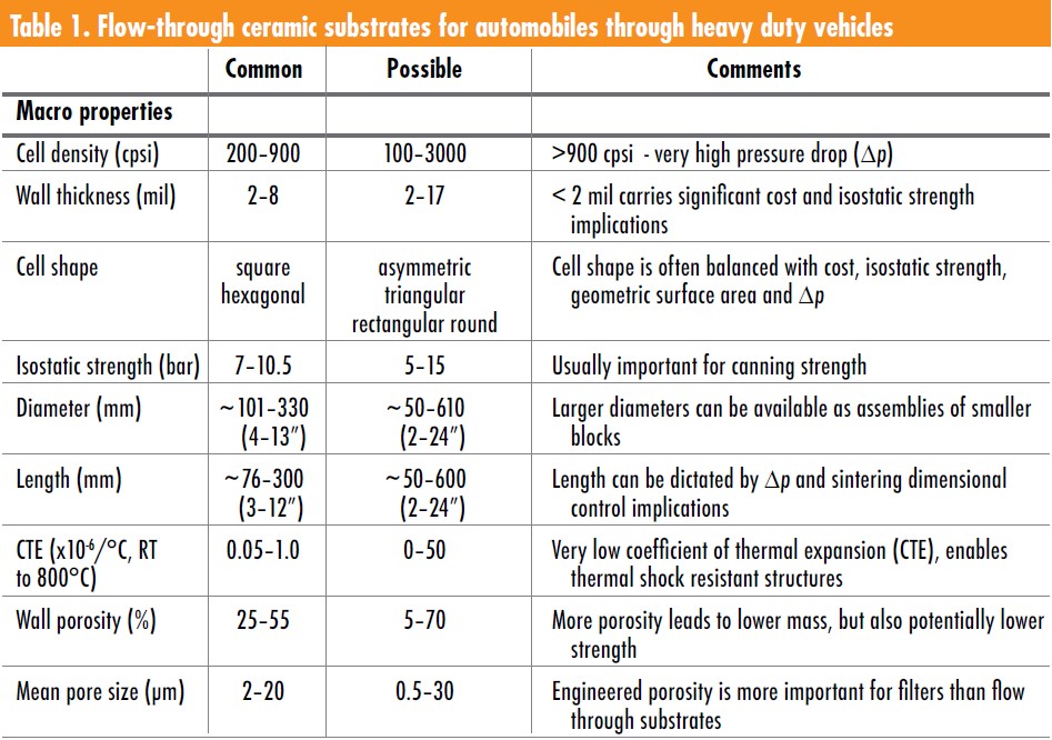
For historical reasons, substrates are commonly referred to by their cell density/wall thickness moniker. For example, a 400/4 substrate is one in which the “400” defines the cell density in cells/in2 (or cpsi) and the “4” defines the nominal wall thickness in 0.001” increments (or mils). In the average U.S. gasoline engine sedan, there are two or three substrates at work to meet the rigorous U.S. gaseous emissions standards. Right off the engine, close-coupled substrate(s) with high cell density (750/2 or 900/2) provide a lot of geometric surface area to allow the catalyst to do the initial gaseous conversions. In the underfloor position there is generally a lower cell density substrate like 400/4, to help clean up final emissions. Table 1 describes common macro and micro properties of ceramic substrates and filters.
Development of particulate filters
The flow-through honeycomb substrate was the ideal platform for supporting catalysts that eliminate harmful gaseous air pollutants but did little to remove harmful particulates from exhaust. Particulates in exhaust are often the result of incompletely combusted fuel and influenced by varied factors including, but not limited to, ambient temperature, altitude, fuel quality, vehicle power-to-weight ratio, drive cycle, and engine hardware and software. The World Health Organization (WHO) cautions that microscopic carbon particles, when inhaled, “can penetrate the lung barrier and enter the blood system. Chronic exposure to particles contributes to the risk of developing cardiovascular and respiratory diseases, as well as of lung cancer.”8
In the late 1970s, an aluminum manufacturer asked Corning if they had a product that could be used to filter impurities from molten aluminum. Corning scientist Rod Frost, who had led the development of the process for producing the ceramic honeycomb substrate, conceived of the wall-flow particulate filter as a possible solution for this application.
As sometimes happens in R&D, the concept did not work for this particular application. However, months later, diesel engine manufacturers came to Corning looking for a concept to filter soot particles from diesel exhaust for diesel engines running in confined spaces, like mining vehicles. Rod thought his ceramic-based wall-flow concept might work better for this application. He had some prototypes made and testing proved his design worked very well.
Corning DuraTrap filters are still produced with the Frost design, as are almost all other particulate filters. These filters have a cellular honeycomb ceramic with engineered wall porosity to capture fine particles. Individual channels are open and plugged at alternating ends, like a checkerboard. Exhaust gases enter the open (inlet) channels, flow down the channel, and escape only through the engineered porosity of the cellular walls. The walls offer little flow resistance and particles become trapped in the porosity and collect on the filter walls instead of being released into the atmosphere. The cleaned gas exits the filter through the adjoining (outlet) channels. Filters can be used in their bare state, or in conjunction with catalysts to assist in gaseous-emissions reduction, or to aid soot burning.
Diesel engines often produce a lot of soot particles, from both a particle number and a mass perspective. This particle output, combined with low engine-out temperatures, often results in a soot cake on the inlet wall surfaces of the wall-flow diesel particulate filter (DPF). The porous deposit of nano to submicron soot particles on the filter wall can increase the native filtration efficiency (Figure 4). The same mechanism operates in gasoline particulate filter (GPF) applications, where the number of particles in the exhaust can be high but the particles have less mass. Collecting a soot cake in gasoline applications is more difficult and typically does less to aid filtration.
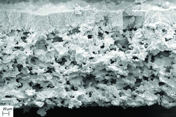
Figure 4. Pictured is a cross-section of a cell wall of a diesel particulate filter, showing an accumulated ash layer at 200x on top of the porous ceramic wall. Credit: Corning Incorporated
In both diesel and gasoline applications, the captured particles remain in the filter until exhaust conditions are appropriate to burn the particles to “clean” or “regenerate” the filter. Regenerating wall-flow filters can take place passively (as a by-product of the time/temperature/atmosphere) or actively (triggered by additional sensors and software). For example, in the diesel case, active regeneration increases the filter inlet temperature in the presence of the appropriate oxygen-containing species to burn the combustible particles, returning the filter to its nearly clean state. Filters generally last the life of the vehicle.
The selection of filter materials depends on the filtration efficiency requirements (microstructure) and the heat capacity requirements (material choice, porosity, cell density/wall thickness). For gasoline vehicles and many heavy-duty diesel vehicles, where passive regeneration dominates, cordierite is the material of choice due to its low cost, low heat capacity, high-melting-point, low CTE, and low-thermal-conductivity with macrostructural and microstructural flexibility.
In some diesel applications, particularly in the diesel passenger car segment, the mass of the soot collected is high, resulting in the possibility of higher exotherms when the filter is regenerated. The heat generated only has two paths to dissipate. It can be carried away in the exhaust gas or is adsorbed by the filter. In regeneration conditions with little exhaust flow, high-heat-capacity alternatives to cordierite, such as silicon carbide or aluminum titanate, are used to adsorb the exothermic reaction to prevent filter damage.
How these products are used in the system
Ceramic substrates and filters are the keystone of mobile pollution control ecosystems. The vehicle emission system is composed of ceramic substrates and filters and ceramic-based catalysts held in place by a ceramic-based mat material. The ceramic substrates and filters provide a thermal-mechanically-stable base that can withstand extremes in temperature and vibration and last for the life of the vehicle. In the case of filters, they also provide the engineered microstructure that allows for the particulate filtration function. All flow-through substrates and, in many cases, wall-flow filters are sent to catalyzers to apply a washcoat and catalyst. These catalysts can be platinum-group metal-based catalysts supported on high surface area alumina, ceria, zirconia, zeolite, or can be other catalysts or sorbents.
After coating, the composite product is sent to a canner and wrapped in a ceramic-based mat material (Figure 5). The ceramic-based component must have sufficient isostatic strength to withstand the canning process, where the material is squeezed (stuffing process) or compressed (tourniquet process) into the can. The ceramic-based mat provides heat insulation and a holding force to maintain the ceramic in the can while it accommodates the differential shrinkage between the ceramic (low expansion) and the metallic can (high expansion). The canned system is then welded into the complete exhaust system and integrated with sensors, so that computers on the vehicle assure the emissions are compliant under all conditions.
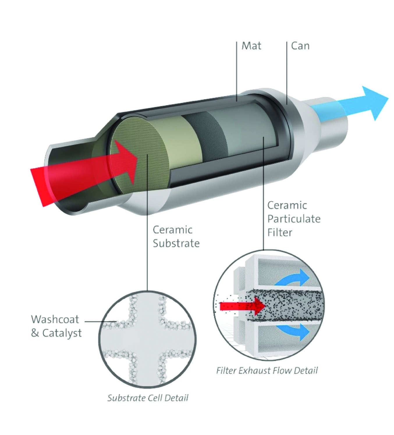
Figure 5. Ceramic substrates and filters and ceramic-based catalysts held in place within a metal can using a ceramic-based mat material. Credit: Corning Incorporated.
Innovation continues
The growth of pure electric vehicles—which have no tailpipe emissions issues (although issues exist at the electricity source and from the braking system)—are changing the baseline and societal expectations. However, even with aggressive battery electric vehicle penetration, the combination of geographic expansion of regulations and regulation tightening in existing regions is likely to increase ceramic substrate and filter volume over the next 10 to 15 years. To stay competitive, some internal combustion engine-based vehicles are going well beyond regulatory requirements—to nearly emissions free—to meet consumer expectations.
Because of advancements in engine, vehicle, and emissions control, the capacity exists to make vehicles achieve “negative emissions” after the first couple of minutes of vehicle operation in many cities, meaning that the air coming out of the tailpipe is cleaner than that going in.
Most of the gaseous and particulate emissions in a typical drive cycle are produced in the first minute or two of operation. Once catalysts are hot, they are extremely effective. Therefore, the remaining frontier of a zero-emission internal combustion vehicle is tackling this first minute of operation, including vehicles with multiple engine starts like start/stop vehicles and hybrid vehicles, which may switch between electric and conventional engines several times during the drive cycle. Due to low engine outlet temperatures (increased engine efficiency or frequent starts and stops), active devices may also play a role.
Current designs and materials for ceramic-based substrates, filters, catalysts, and mats will continue to play an important role in meeting future requirements. However, new ceramic processes, materials, microstructures, and designs will be needed to enable products that heat-up faster and have higher pollution removal efficiencies. Thinner walls, higher porosity levels, tighter pore size control, and additional durability are all on the list.
Cellular ceramics proved to be an effective way of packing a lot of geometric surface area into a small volume, and the cellular form factor is an important success factor for mobile emissions remediation (Figure 6). There are likely benefits for cellular ceramics beyond mobile emissions as similar benefits may extend to catalysis, sorption, and filtration in other industries such as petrochemicals, fine chemical, clean water, and more. For these reasons, ceramic filters and substrates are likely to remain a key factor in the improvement of the environment around the world.
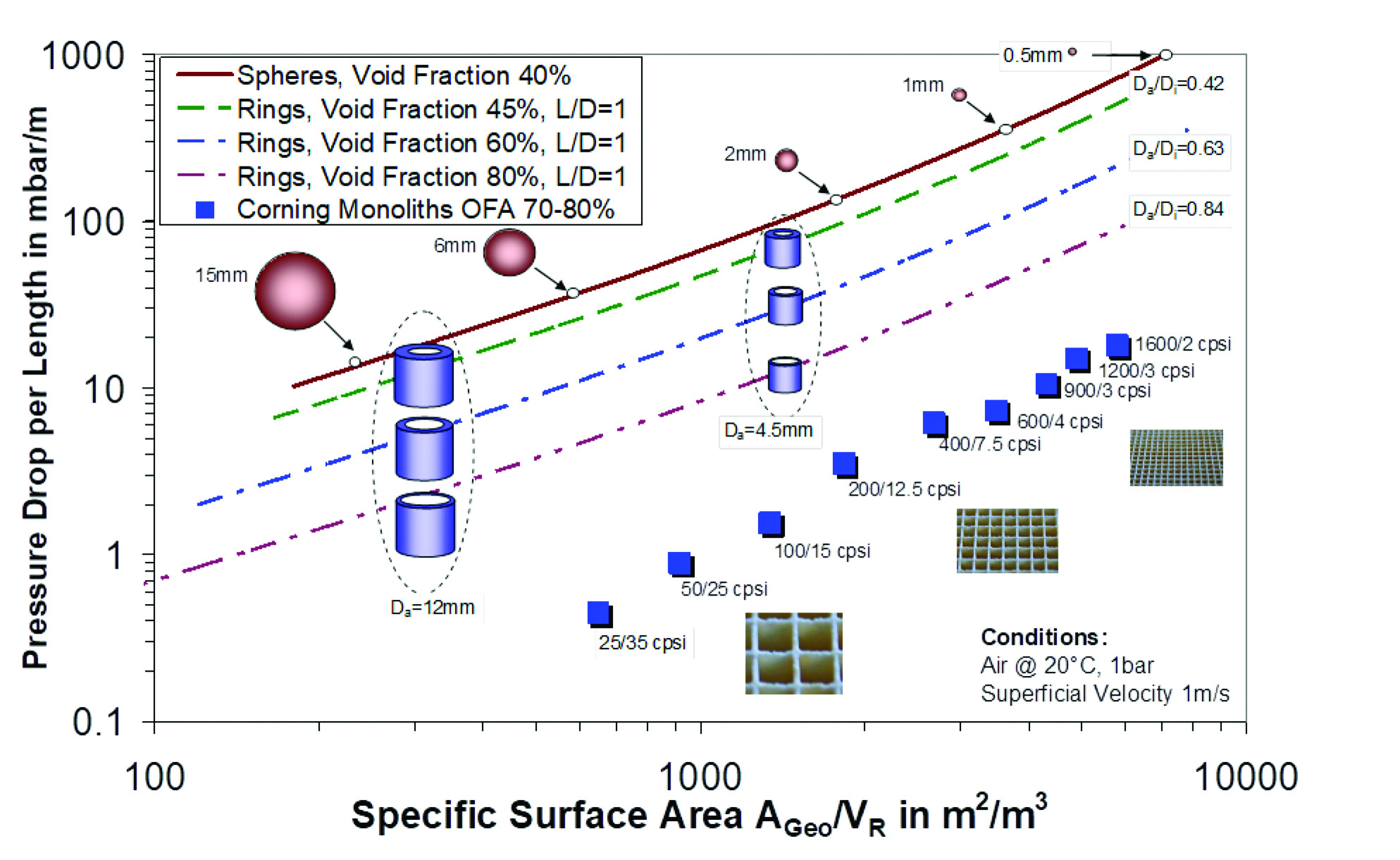
Figure 6. Pressure drop as a function of specific surface area for various form factors of media, where L is ring length, D is ring diameter, and OFA is open frontal area. Credit: Cutler
Regulations, impact, and societal benefits
Over the past nearly 50 years, ceramic substrates and filters brought dramatic benefits to society. Since the U.S. adopted the Clean Air Act of 1970, the nation’s economy grew fourfold. At the same time, ambient air pollution dropped more than 70%. The greatest contributor to this improvement in air quality—reduced vehicle emissions—is largely due to the three-way catalytic converter, so called because it mitigates NOx, CO, and hydrocarbon. With the addition of the wall-flow filter, in some locales the air coming out of the engine can be cleaner than air going into the engine.
The success of Clean Air Act standards in its early years gave the EPA impetus to add even more-stringent amendments in 1990. These standards, according to government studies, are saving an additional 160,000 lives per year. The 1990 law also prevents an estimated 13 million lost workdays, 1.7 million cases of exacerbated asthma, and roughly 130,000 cases of heart disease each year.1 Beyond these benefits, the emissions-control systems turned out to be a bargain for automakers as well. Catalyst systems represent less than 5% of the sticker price of most vehicles, and the societal benefit—even as regulations became more stringent over the years—is still about $10 for every $1 spent.
Regulations for heavy-duty vehicles and nonroad machineries were also adopted, expanding ceramic substrates and filters to larger vehicles and increasing component size up to 20 times larger than light-duty vehicles, requiring new manufacturing developments to make ceramic structures and catalyze the large-frontal area substrates and filters.
The honeycomb ceramic substrates and filters had such a profound impact on air quality that in 2002, the National Inventors Hall of Fame inducted the three Corning scientists who developed the innovation: Dr. Irwin Lachman, Dr. Rod Bagley, and Mr. Ron Lewis. They were recognized for creating the extrusion method for forming the thin-walled structures. And in 2005, those same three scientists won the National Medal of Technology.
What’s ahead?
Despite the short-term fluctuations of governments, the overall global direction is toward tightening standards for vehicular emissions. This attention to air quality intersects the continuing increase in vehicle usage. Many forecasts indicate vehicle growth of up to 50% over the next 20 years. Virtually all this growth will be in heavily populated and developing countries.
Following this trend, expect to see the eventual expansion of regulations in the Asean and Africa regions, as well as the tightening of regulations in emerging economies. China, India, and South America now are implementing vehicle tailpipe regulations on par with those in Europe but still with looser gaseous emissions than in North America. Because the technology is already available to make the air even cleaner and easily deployed, for example, from the U.S. to Europe, further regulatory tightening in all regions is quite likely.
Though vastly improved over the past 50 years, air quality in the U.S.—specifically, in large cities and traffic-heavy California—still has room for significant improvement. Reductions in real world driving emissions for NOx and particulates are still needed. Some in California are exploring new standards that would enable the use of gasoline particulate filters, matching the low particulate output of European and Chinese gasoline vehicles.
Improvement also continues in long-term emissions standards for heavy-duty vehicles. Some California lawmakers are working to tighten NOx emissions by more than 90% by 2027 to address urban ozone issues. They are also considering doubling or tripling the regulatory full-useful life and emissions warranty for trucks and other heavy-duty equipment. Similar initiatives are in the works in Europe and China.
Acknowledgements
The authors would like to thank Tim Johnson, Anne Kenlon, Kerstin Stobbe, and Agatha Lutoborski for their help with this article.
Capsule summary
A dirty problem
By the mid-1900s, health hazards associated with poor air quality had come into stark view. Governments set new federal air pollution regulations that presented both a technological challenge and business opportunity for industry manufacturers.
Ceramic solution
In the 1970s, Corning scientists invented a substrate for catalytic convertors based on cordierite and also a ceramic-based wall-flow particulate filter for diesel engines. Nowadays, ceramic substrates and filters are the keystone of mobile pollution control ecosystems.
Innovation ahead
Most emissions in a typical drive cycle are produced in the first minutes of operation, so the remaining frontier of a zero-emission internal combustion vehicle is tackling this first minute of operation.
Read more: “Clean Air Act of 1970“


Related Articles

Market Insights
The evolving discipline of demand forecasting can improve competitiveness and control costs
What does the future hold? It is a question that everyone has contemplated at one time or another, and a mystery that has obsessed writers, mystics, philosophers, clerics, astrologers, and others for centuries. For businesses, the question is more than philosophical. Discovering clues to what is next is essential to…

Bulletin Features
Sustainable ceramics production: Environmental considerations in tile manufacturing
Ceramics are often regarded as a sustainable material choice thanks to their high durability and chemical stability, which enable a long service life. But ceramics come with environmental baggage in other areas, such as raw material sourcing, processing, and disposal. The specifics of this baggage are unique to each ceramic…

Market Insights
Financing the responsible supply of energy transition minerals for sustainable development
As the world transitions to sustainable development and the achievement of net-zero emissions by 2050, the demand for specific minerals and metals, such as lithium, nickel, and copper, is surging. These minerals are crucial for the development of batteries, solar panels, and electric vehicles, and therefore are central to clean…