
Binders have been used in 3-D ceramic printing processes since the 1980s. For example, a 3-D printing process developed by Yoo et al.1 selectively prints latex binder after a layer of submicron alumina powder is spread evenly on a flat “table.” Binders also may be useful materials for printing 3-D ceramics on the moon and Mars using available materials, because adhesive materials are already routinely used by astronauts.2
To achieve in situ resource utilization goals for space exploration missions, new techniques are needed to allow affordable and sustainable human exploration to deep-space destinations. For many manufacturing processes on earth, printed green bodies can be heat-treated in furnaces. However, for in situ manufacturing processes on the moon or Mars, selective laser or light sintering of 3-D parts may be more feasible than heat treatment in a furnace. Another important consideration is the ability to use materials present at the destination for necessary exploration and survival functions.
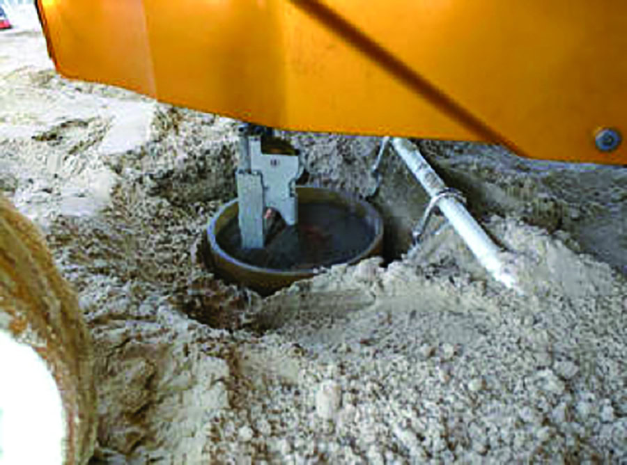
Figure 1. (b) Resource Prospector can drill into the ground to collect soil samples. Credit: NASA
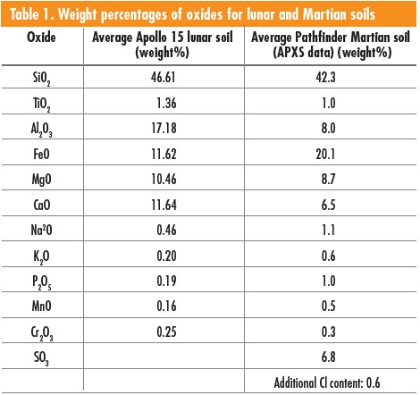
In 2020, NASA will send a utility vehicle called “Resource Prospector” to the moon, where it will “drill” into the ground and collect soils (Figure 1).3 This expedition will provide useful information about the compositions of lunar (regolith) soils, although some information is already known from past missions. For average Apollo 15 soils with grain sizes of <1 mm, Table 1 shows tabulated weight percentages of metal oxides.4–5 In addition, a NASA reference publication documents grain sizes of lunar soils.6 For example, Figure 2 plots weight percentage as a function of sieve size for soil sample No. 75080, showing that approximately 91% of grains have sizes of <1 mm. For Martian soils, weight percent ages of compositions can be derived from alpha-particle X-ray spectrometer (APXS) techniques, as illustrated in Table 1.7
Due to the extreme environment of space, materials used in space applications must be carefully designed and tested for their specific application. For example, adjusting fabrication conditions can vary the porosity of samples. Further, mixing alumina with frit or coating alumina with glazing materials forms additional glass phases, adding another dimension of control and variability to these materials. Exposing alumina to radiation similar to that of outer space will reduce its bulk electrical resistivity,8 while exposing glasses to radiation creates bubbles.9–11
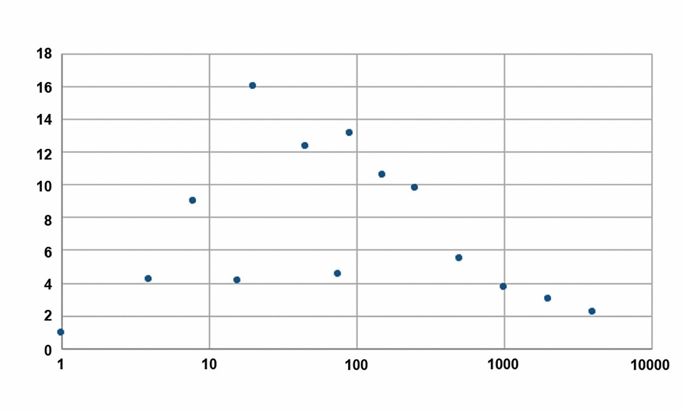
Figure 2. Weight percentages and sieve sizes for lunar soil No. 75080 (data from J. C. Graf, “Lunar Soils Grain Size Catalog”). Credit: J. C. Graf and Xingwu Wang
Before considering 3-D printing ceramics from lunar or Martian simulant soils, we conducted binder jetting experiments with aluminum oxide, silicon oxide, calcium oxide, and sodium oxide materials. For these experiments, we focused on alumina-based materials because of their potential of use in small functional devices.8–13 However, lunar or Martian soils are silica-based materials, which we are currently preparing for future printing and analysis studies.
Ink jetting simulant soils
We used two commercially available ink jet printers—ExOne binder jetting machines Innovent and M-Flex—to compare material batches and techniques and to fabricate samples for radiation damage experiments aboard a scheduled outer space flight. Our working theory is that the binders will be used to 3-D print in space, as they are more suitable in low gravity or low atmosphere manufacturing environments.
Although both printers are based on the same technology principles, the end uses are different. As far as this study is concerned, Innovent is used for small sample sizes and limited number of samples, while M-Flex is used for large sample sizes and more samples. When 3-D printers are sent on outer space missions, smaller printers will be favored because of their substantially lower shipping costs compared to larger printers.
The printers can print one layer in 0.5–1.0 min, with a layer thickness of ~100 µm. Maximum dimensions for Innovent printed objects are 16 cm × 6.5 cm × 6.5 cm, while those for M-Flex are 40 cm × 25 cm × 25 cm. ExOne uses a “solvent-based” binder that we used to print various objects.
We printed various shapes, including discs, washers, bars, and simple sculptures. Figure 3 shows a cylindrical-shaped object with different sized holes (outer diameter =~5 cm; height =~3 cm), which can be used for humidity sensors and chemical sniffers.
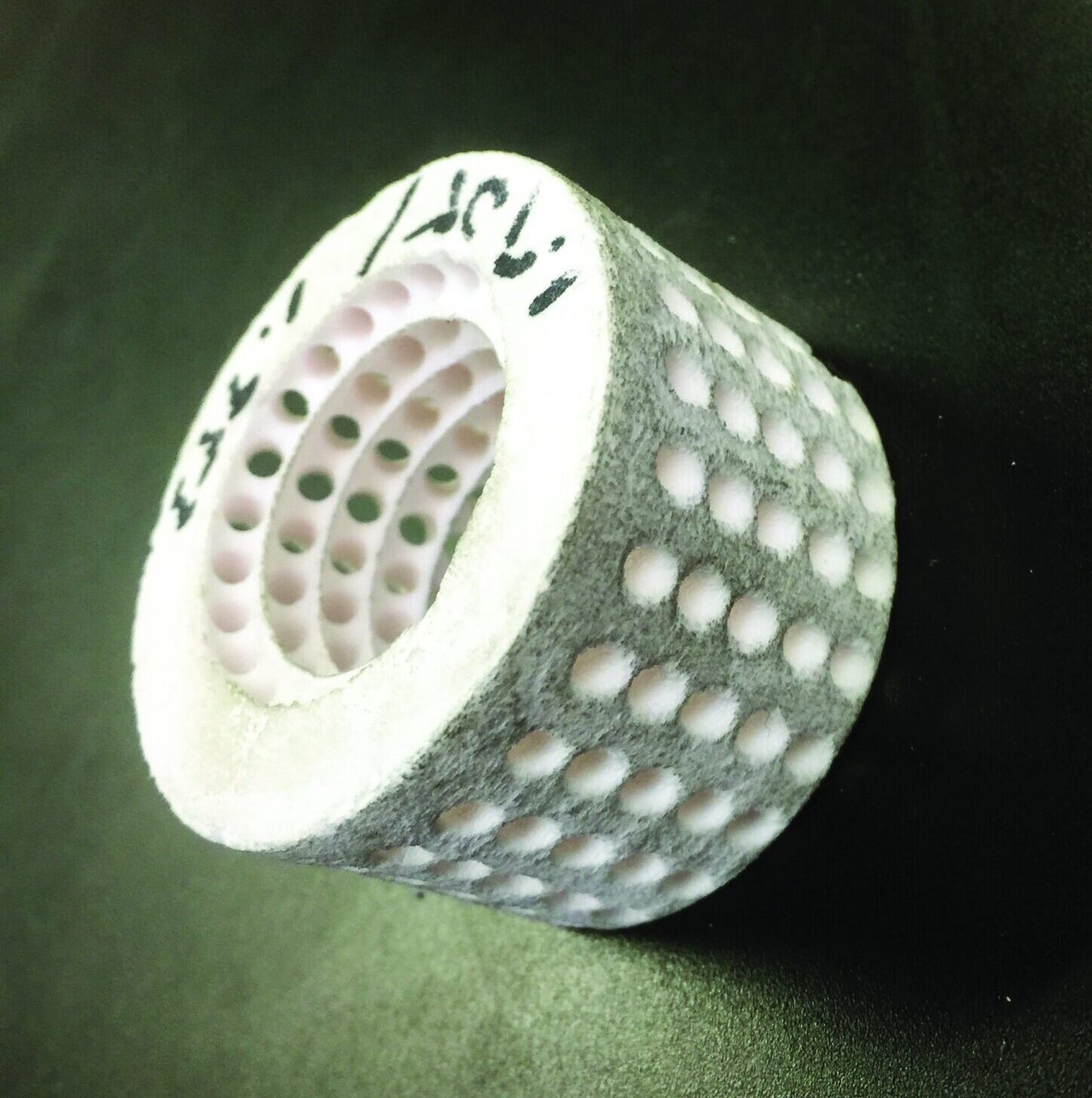
Figure 3. 3-D-printed ceramic object, with an outer diameter of ~5 cm, and height of ~3 cm. Credit: David Crenshaw
We prepared two batches of printing materials with different porosity distributions and glass phases in grain boundaries: batch A has a uniform porosity distribution, while batch B has denser sample surfaces than interiors. In terms of glass phases between alumina grain boundaries, batch A has relatively uniform distributions throughout, while batch B has more surface distributions than interior distributions.
These differences may be useful for radiation damage testing. First, glass bubbles created by radiation on the surfaces of samples will be more apparent for samples from batch B than batch A. Second, reductions in resistivity caused by radiation will be more apparent for batch A than batch B.
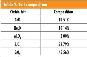
We prepared batch A from precursor materials composed of 80 wt% fused alumina (25 µm, Electro Abrasives) and 20 wt% calcia-borosilicate frits (400 mesh, Ferro 3134). Table 2 lists tabulated frit compositions. Table 3 shows the heating profile, with a heating rate of 5°C/min for each step. After the last step, the furnace was turned off and allowed to cool to room temperature.
To prepare batch B, we used the same fused alumina as batch A to print 3-D objects, which were then dip-coated with clear glaze materials (56% boric acid, 3.44% soda ash, 8.94% whiting, 13.41% flint, and 17.88% EPK kaolin; SiO2, B2O3, Al2O3, MgO, CaO, and Fe2O3). Objects were heat-treated at a maximum temperature of 1,500 C.
The role of glaze was two-fold: to create a denser surface than interior, so that samples can withstand vibration during lift-off from earth; and to create different glass phase distributions to obtain different radiation damage signatures, including creation of bubbles in glass phases and reductions in resistivity.
The processing method for both batches is relatively cheaper and easier than other methods, such as hot isostatic pressing or melt infiltration. Our goal was to achieve appropriate surface or bulk porosity to allow testing in outer space while guaranteeing sample integrity during lift-off.
Analysis of printed materials
For batch A, the average porosity is 0.28±0.02, with a mass density of 2.56±0.06 g/cm2. For batch B without dip coatings, the average porosity is 0.46±0.02, with a mass density of 1.34±0.03 g/cm2.14 Therefore, these porous materials could have space applications such as radiation detectors, humidity sensors, and chemical sniffers.8–13
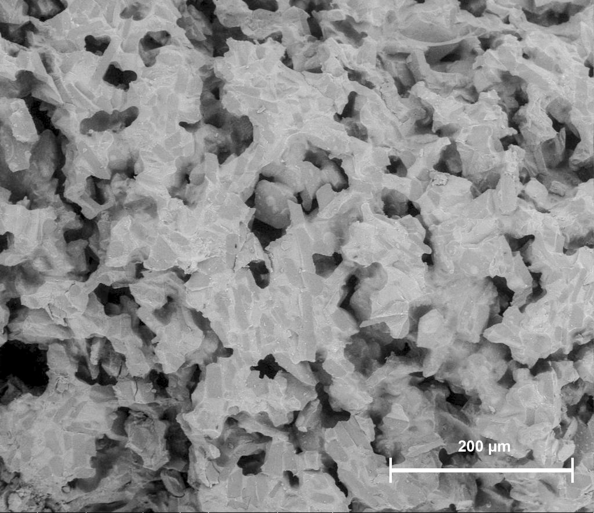
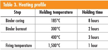
Figure 4. Scanning electron micrograph of a fracture surface of a batch A sample, prepared for testing the effects of outer space radiation.
Scanning electron microscopy images of batch A samples show the baseline condition of the 3-D-printed structure prior to testing in space. Figure 4 shows the typical pore size and distribution. A higher magnification charge contrast image in Figure 5 illustrates a glassy phase (labeled A) that will be monitored for the effects of radiation exposure and a representative alumina grain (labeled B). The area inside the rectangle is shown at still higher magnification in Figure 6. Because this area is expected to experience the most change per unit volume due to radiation damage, we will monitor this area closely during in-flight testing.9–11
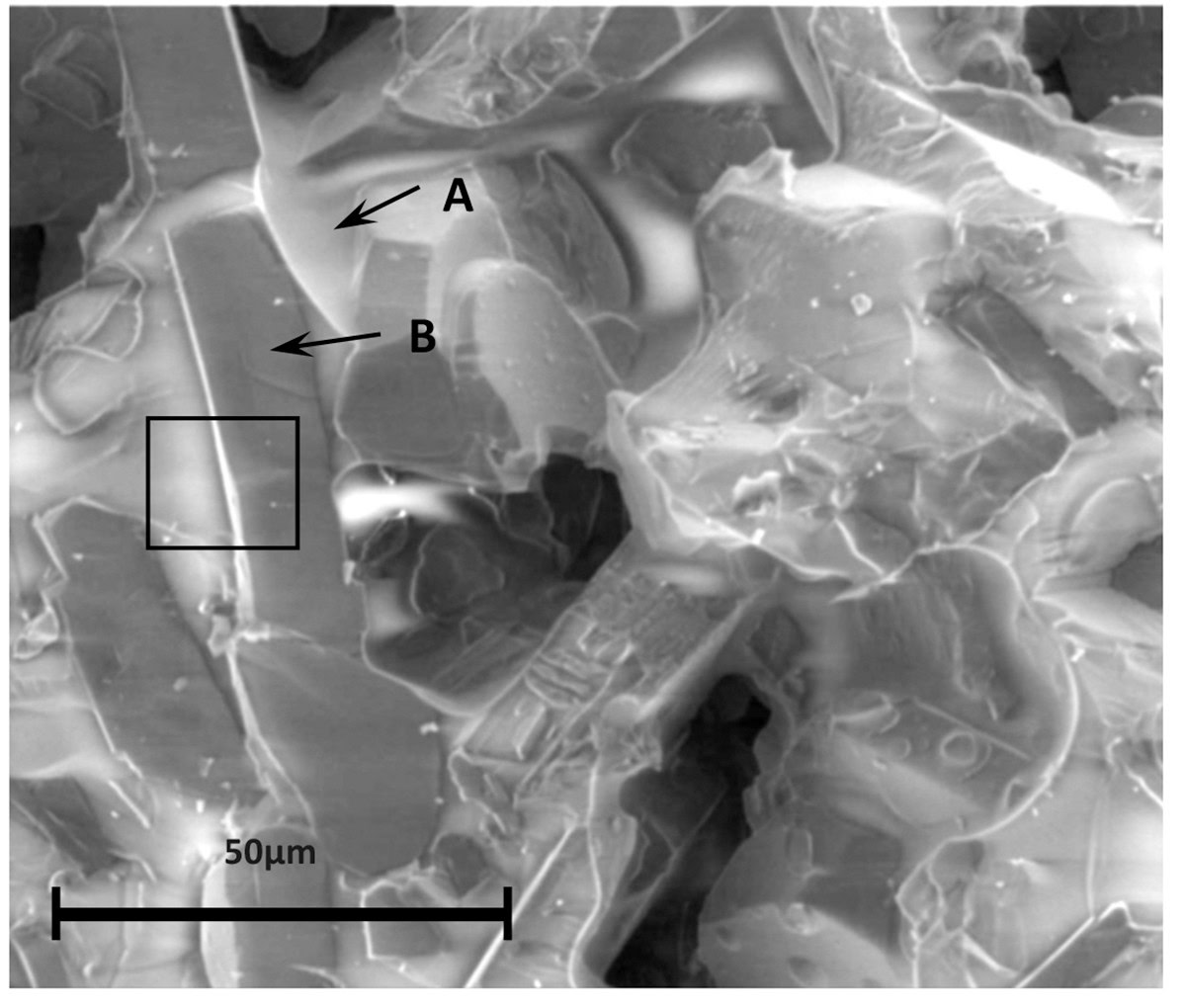
Figure 5. Higher magnification of a scanning electron micrograph charge contrast image showing a glassy phase (A), which will be monitored for the effects of radiation exposure, and a representative alumina grain (B) in a batch A sample. The area inside the rectangle is enlarged in Figure 6. Credit: Gerry Wynick
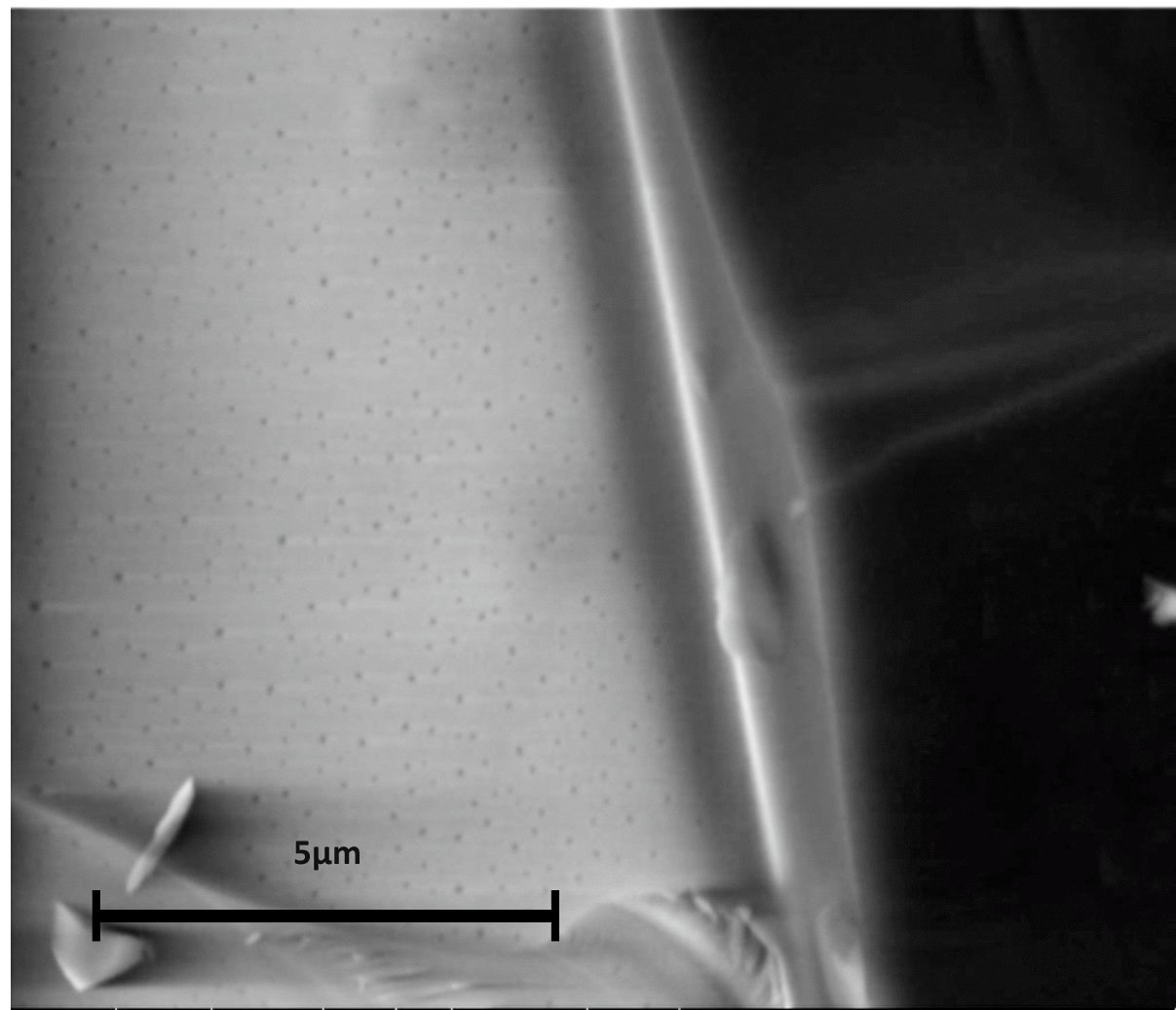
Figure 6. Higher magnification scanning electron micrograph of batch A sample showing the area within the rectangle in Figure 5. Credit: Gerry Wynick
Energy-dispersive X-ray spectroscopy (EDS) of batch A detected Al, Si, Na, and O signatures (Figure 7). X-ray photoelectron spectroscopy (XPS) of the same sample revealed Al, Si, Na, Ca, O, and C signatures (Figure 8).15 The carbon signature may be mainly due to sample handling and possibly related to residual carbon from organic binder materials that require more extensive heat treatment processes, such as longer furnace holding times. Other signatures are all related to precursor materials.
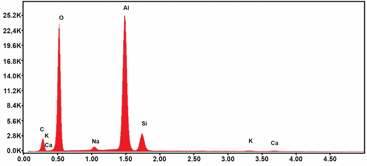
Figure 7. Energy-dispersive X-ray spectroscopy spectrum of 3-D-printed batch A sample, showing Al, Si, Na, and O signatures. Credit: Gerry Wynick
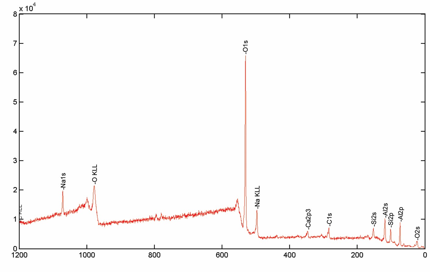
Figure 8. X-ray photoelectron spectroscopy spectrum of batch A sample, showing Al, Si, Na, Ca, O, and C signatures. Credit: Jim Thiebaud
For batch B, an SEM (top-view) image in Figure 9a shows much larger pore sizes than those batch A. Viewing a similar surface with larger magnification more clearly reveals glassy phases among polycrystalline phases (Figure 9b,c).

Figure 9a. Scanning electron micrograph of top view of a batch B sample. Scale bar represents 1 mm. Credit: Gerry Wynick
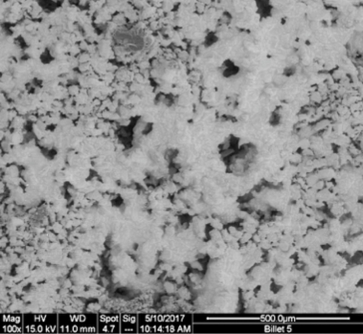
Figure 9b. Higher magnification scanning electron micrograph of top view of a batch B sample. Scale bar represents 500 µm. Credit: Gerry Wynick
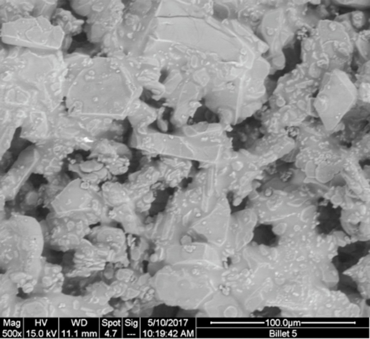
Figure 9c. Higher magnification scanning electron micrograph of top view of a batch B sample. Scale bar represents 100 µm. Credit: Gerry Wynick
In-flight testing in outer space
These 3-D-printed samples will be exposed to outer space environments for six months aboard the Japanese External Module – Exposed Facility (JEM-EF). A dozen samples will be assembled in holders and placed in a Craig-X flight test platform (Figure 10), which will be mounted inside the NanoRacks external platform located on the back side of the JEM-EF.
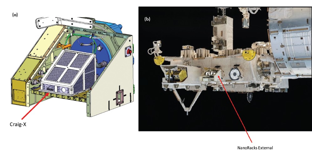
Figure 10. A dozen 3-D-printed samples will be assembled in holders and placed in a Craig-X flight test platform (a), which will be mounted inside of the NanoRacks External Platform (b) located on the back side of the Japanese External Module – Exposed Facility. Credit: Ryan Jeffrey and Carol Craig
The tentative launch date for this mission is late 2018 or early 2019. After being launched into outer space, samples will be exposed to outer space environments for six months. During that period, certain satellite environments can be obtained via the National Oceanic and Atmospheric Administration websites.
In six months, cumulative radiation exposure amounts can reach approximately several joules to several hundred joules. Assuming the mass of a glass phase is <1 mg, the radiation exposure or dosage will exceed several million Gy, which can cause radiation damage to glasses as disclosed in earlier studies.10–11 This damage, known as radiolytic bubble formation, can be divided by three different sources: gamma, ion, and electron irradiation.9
After six months of exposure to outer space during flight, the 3-D-printed objects will be reexamined via SEM. Once we separate damage in the samples due to electron beams in SEM, we will be able to establish damage to the materials due to outer space radiation. Then we will compare the electrical resistivity of 3-D-printed alumina samples with or without radiation exposure. Earlier studies indicate that radiation can permanently reduce alumina resistivity.8 Thus, radiation detection may be achievable through resistivity measurements and/or analysis of bubble formations in glass phases. Importantly, resistivity is used as a signature in designs for sensors, detectors, and sniffers.
Many factors should be considered for outer space experiments, including: packaging for ceramic samples, changes in temperatures and humidity, and vibrations during rocket launch. Therefore, we will assess sample sets via three tests. The first set of samples will be wrapped with Gore-Tex fabric with pore sizes of ~10 µm and will be examined by “drop tests.” The second set will be tested on a mechanical shaking table with varying amplitudes, velocities, and accelerations. The third set will be placed in a “environmental chamber” with temperatures varying between –250°C and 300°C, and humidity varied between 100% and 0%.
Samples that pass these three tests will be used as prototypes for humidity and gas sensing applications.12–13 Additionally, preflight testing will be used to purposely select better samples for outer space flight experiments and ensure that the samples can survive launch and flight conditions.
While there is no published cost of payloads to the moon or Mars in the public domain, the cost to the International Space Station (ISS) provides a reference. Currently, cargo shipping cost to the ISS is estimated to be $20k–$60k per kilogram, with a future-targeted goal of ~$2k per kilogram.16 Thus, if raw materials for missions to the moon or Mars can be obtained on site, shipping costs could be substantially reduced. Further, beyond small devices such as radiation detectors, humidity sensors, and chemical sniffers, large amounts of raw materials will be needed for human habitats based on ceramics.17
Future missions
Binders connecting metal oxides provide a material solution to explore the possibilities of future 3-D printing endeavors in lunar and Martian missions. As an early step towards these possibilities, this preliminary work included three parts:
- Studying lunar/Martian soils that may contain various metal oxides and small particle sizes;
- Fabricating alumina-based 3-D ceramic samples via binder jet printing technologies; and
- Exploring opportunities to test these samples in an outer space experiment.
As a next step, we are conducting additional experiments to fabricate and characterize samples for testing. Further, we are using mathematical models to study the economic impacts of 3-D-printed ceramics for space exploration missions.
Acknowledgements
The authors thank the following personnel in various organizations for their help and support: Nick Studley, Linda Crum, Jesse Blacker, and Gabe Doman (ExOne); Mike Hall (MARS Habitat); and provost Rick Stephens, dean Alastair Cormack, professor William Carty, Jim Thiebaud, Jennifer Zheng, Elizabeth Walsh, Kyle Silbstein, and Avery Sandler (Alfred University).
Capsule summary
To infinity and beyond
Establishing exploratory bases on the moon or Mars will require small, functional ceramic components such as radiation detectors, humidity sensors, and chemical sniffers. Eventually, larger structural components will be needed to build human-worthy habitats.
Ship machines, not soils
Shipping components to outer space destinations is expensive and limits inventory on site. Additive manufacturing with “local” soils allows custom building of parts as needed.
Will it work?
Because of low gravity, binders will be essential, but how will they behave? How will 3-D-printed parts respond to the harsh radiation environments of outer space? An experiment scheduled for the International Space Station* plans to answer some of these questions.
* ISS operates in low earth orbit.


Related Articles

Market Insights
Engineered ceramics support the past, present, and future of aerospace ambitions
Engineered ceramics play key roles in aerospace applications, from structural components to protective coatings that can withstand the high-temperature, reactive environments. Perhaps the earliest success of ceramics in aerospace applications was the use of yttria-stabilized zirconia (YSZ) as thermal barrier coatings (TBCs) on nickel-based superalloys for turbine engine applications. These…

Market Insights
Aerospace ceramics: Global markets to 2029
The global market for aerospace ceramics was valued at $5.3 billion in 2023 and is expected to grow at a compound annual growth rate (CAGR) of 8.0% to reach $8.2 billion by the end of 2029. According to the International Energy Agency, the aviation industry was responsible for 2.5% of…

Market Insights
Innovations in access and technology secure clean water around the world
Food, water, and shelter—the basic necessities of life—are scarce for millions of people around the world. Yet even when these resources are technically obtainable, they may not be available in a format that supports healthy living. Approximately 115 million people worldwide depend on untreated surface water for their daily needs,…