
In the world of wireless communication, 5G has become almost a pop-culture reference. It is a term frequently used to describe improved handsets, devices, and infrastructure enabling faster speeds and more bandwidth. This article presents a cursory overview of what 5G is, what are the technical pillars of 5G systems, and finally, the role ceramic materials will play in 5G technology.
To recount the history of wireless telephony, 1G systems, introduced in the 1980s, were full analog systems. These were very large, expensive devices that were essentially luxury items. 2G systems launched in 1991, and these systems were the first to use digital signals in GPRS and EDGE technologies. 3G systems launched in 2001 and had faster data rates and increased use of digital signals relative to 2G. The 2G and 3G systems featured a device called an auto-tuned combiner in the base station that selected frequencies with the use of an ultra-low loss tangent microwave dielectric material for both the analog band (< 1 GHz) and the digital band (near 2 GHz). The current 4G technology came into play around 2011 and did not use the auto-tuned combiner. Metallized ceramic dielectric rods are used for filters in the base stations for this technology. As of today, networks strain under by the current demand in the 700 MHz–2.7 GHz range. New technologies need to be deployed to utilize faster data rates needed for modern wireless communication including the Internet of Things (IoT).
Figure 1 shows a schematic illustrating features of 5G communication. Among the benefits of 5G communication are higher data rates (10 times faster than 4G), low latency (no delays between transmit and receive signals or no dropped calls), and increased connectivity (including humans and machines). In fact, 5G systems are expected to be able to handle more than 1,000 times the number of connected devices that exist today. One fundamental technical feature of 5G systems is the use of spectrum at frequencies above which current 4G systems operate. The 5G system will operate in two different bands: a lower frequency band at 3–6 GHz, and a higher frequency band in the millimeter wave region (20–100 GHz). This lower frequency band is adjacent to spectral regions currently used for 4G systems. Although there will be some modifications in the technology used in the lower band relative to 4G systems, the modifications will not be as drastic as the technological changes required to make millimeter wave handsets and devices.
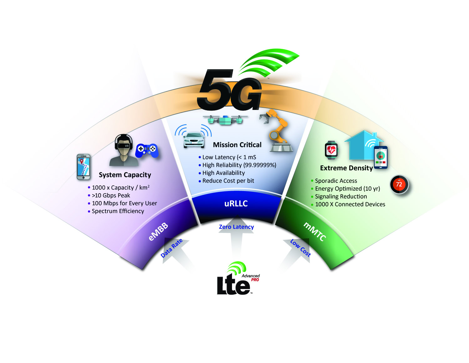
Figure 1. Representation of advantages of 5G systems over current systems. Credit: Courtesy of Skyworks Solutions
5G requirements
Millimeter waves: There are a number of key technologies for 5G systems. The millimeter wave region is attractive in that there is so much “spectrum” available above 10 GHz. Bandwidth considerations therefore cease to be an issue for the time being. Among the frequencies being examined for devices are 28 GHz and 39 GHz. However, along with this “open range” of spectrum come some serious technical challenges. One of the largest challenges involves the signal range at these higher frequencies. Attenuation is a term used to describe how the strength (amplitude) of a signal decays over distance. This attenuation is a frequency-dependent phenomenon for electromagnetic waves; that is, the higher the frequency, the greater the attenuation and the shorter the distance the wave may travel. Attenuation has major implications on how 5G infrastructure will be deployed. Currently, for systems operating below 3 GHz, large base station towers spaced on the order of fractions of miles apart are sufficient to handle wireless traffic in 4G systems. If, in fact, millimeter wave systems are put in place, the range would be much less and the size of the base station (or repeater, in this case) will have to be reduced. It is possible that centralized towers may still connect base stations to each other in the 3–6 GHz range, and each tower would be surrounded by a number of short-range repeaters operating at millimeter wave frequencies. Or, there may just be a myriad of decentralized small base stations dotting the landscape, connecting with one another. At this point, it is too early to tell how 5G infrastructure will be deployed.
Filtering becomes another concern for 5G systems, particularly for handset applications. Currently systems operating below 3 GHz use acoustic wave filtering. It is possible that this technology may be pushed into the 3–6 GHz frequency band. However, a different type of filtering technology would be needed for applications in the millimeter wave region.
Massive MIMO antennas: The type of antenna technology used for 5G systems is likely to be vastly different as well. Rather than a single antenna transmitting and receiving signal in all directions, 5G architectures will have an enhanced directionality. A directional beam will result in reduced power consumption because all radio frequency (RF) signals will be targeted toward a receiving unit and not scattered in all directions. A directional beam is obtained by using an array of antennas rather than a single antenna. This array, called multiple-input and multiple-output (MIMO), allows for guiding the beam through a combination of constructive and destructive interference to conserve power and focus the signal on a specific device. The efficiency and bandwidth of an individual antenna is a function of its dielectric constant. A lower dielectric constant material will lead to a more efficient antenna. As there will be arrays of multiple antennas embedded in multiple dispersed base stations, there will be a large number of individual antennas required for 5G networks.
Half and full duplexing: For past cellular systems up to 4G, different frequencies are used for the transmit and receive signals, in a technique called diplexing. On the other hand, if the same frequency is used for both transmitting and receiving, the technique is called duplexing. Time domain duplexing (TDD) or half duplexing is a technology to be utilized in 5G systems. The same frequency is used for both transmitting and receiving but they operate at different times. TDD technology requires fast semiconductor gallium nitride switches (particularly at mm-wave frequencies) or nonreciprocal devices such as circulators. Full duplexing technology would involve simultaneously transmitting and receiving at the same frequency and would require a “nonreciprocal” device such as a circulator.
Antennas, filters, and resonators
Ceramic materials are likely to play a role in many 5G systems in both frequency bands.1 Consider individual antennas in use for MIMO applications. As previously stated, MIMO technology will demand multiple individual antenna elements in closely spaced base stations. There will certainly be a demand for inexpensive antennas and for low dielectric constants to improve the efficiency and bandwidth. Polymers and ceramic-filled polymers have the advantage of being inexpensive and having low dielectric constants as well as being easily conformal and integrate-able with established low temperature processes. However, ceramic materials have the advantage of reduced dielectric losses, temperature stable dielectric constants, and improved thermal conductivity for thermal management. Depending on thermal requirements of the architecture and design of the base station, polymer-based or ceramic-based technology will likely be favored. Low temperature cofired ceramic (LTCC) type materials will likely play a large role in some integrated systems containing MIMO antennas. Other advantages of ceramics over polymeric materials include the ability to provide a wider range of dielectric constants, better mechanical stability in thin sections, and the relative ease of metallization.
Filtering technology for 5G systems is very likely to involve ceramic materials as well. Currently, microwave dielectrics are used in filters for base stations while acoustic wave filters (bulk acoustic wave (BAW) and surface acoustic wave (SAW)) are used in handsets. In the 3–6 GHz 5G band, significant changes in the filtering technology for 5G base stations are not expected. In the handsets, there are efforts underway to advance BAW technology up to the 5–6 GHz range although it is questionable whether this technology can be pushed to these higher frequencies. For the mm-wave space, however, the nature of filtering will certainly be drastically different than for sub 6 GHz bands.
It is uncertain exactly what type of filtering will be used for handsets or for base stations in the mm-wave region. It is certain that it would involve electromagnetic field-based devices rather than piezoelectric (acoustic) devices. Waveguide filters or any number of a wide range of architectures may be used for mm-wave filters. A focus at Skyworks is to predict the nature of the dielectric materials expected for mm-wave applications, determine the gaps in the suite of known dielectric materials, and initiate development efforts on these currently undiscovered materials. The predictions for the types of materials required are 1) ultra-low loss tangent materials with dielectric constants below 30, and 2) temperature stable, low dielectric loss tangent materials with dielectric constants below 15.
For the first item, it is useful to bring up the Qf product rule for dielectric resonators. Although this is not exactly applied in any known material, it is a method of getting a crude prediction of the loss tangent for a particular material at a given frequency. The Q of a resonator is the value of the center of the resonant frequency band divided by the width of the resonance 3 dB below the maximum value. In real devices, the Q is a function of the loss tangent of the dielectric material as well as the size of the cavity, the method of affixing the microwave dielectric to the cavity, the proximity to metal, and countless other design related items. Taking the hypothetical case of the infinite cavity, the Q would be equal to the reciprocal of the loss tangent (or dielectric loss) of the material and thus by the “Qf product rule” frequency/loss tangent = constant. As a result, it would be desirable to have ultra-low loss tangent materials (high Q) for mm-wave applications. A material with a low loss tangent of 0.00001 at 1 GHz would have the considerably more modest loss tangent of 0.00028 at 28 GHz (Q of 3,571 in the hypothetical infinite-sized cavity). Therefore, to get materials with appreciable loss tangents in the mm-wave space, it is necessary to look at materials with extremely high Q values near 1 GHz.
In the days of 3G technology, a key component for cellular base stations was the auto-tuned combiner. 3G technologies made use of an analog band for voice transmission below 1 GHz and a digital band near 2 GHz. Q values near 50,000 were required for the materials used for the digital band (corresponding to Qf products near 100,000). In addition to the low loss tangents, the material had to have a temperature-stable dielectric constant as well. Some of the highest Q materials were complex ordered materials with the perovskite structure based on barium magnesium (dielectric constant 25), zinc tantalate (dielectric constant of 30), or barium zinc cobalt niobates (dielectric constant 33–36). Peter Davies in particular has published extensively on the mechanisms leading to high Q in these materials.2 In short, it involves stabilizing defects of all dimensions (e.g., point defects, antiphase domain boundaries) and creating ordered microstructures where extremely high loss-tangent features are not present. In ordered perovskites, antiphase domain boundaries are particularly problematic as reported by Davies et al.2,3 Not only do they create a natural discontinuity to the structure within a particular grain, but they may act as a sink for point defects. One strategy used for barium zinc cobalt niobate is to nucleate a low-loss-tangent second phase at these antiphase domain boundaries. The staple-like features shown in Figure 2 are an example of a high Q microstructure with stabilized domain boundaries.
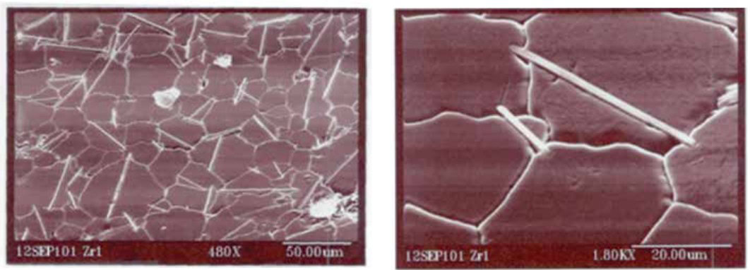
Figure 2. SEM micrograph of intergrowth phases at antiphase domain boundaries in barium zinc cobalt niobate. Credit: Davin Phelps and Mike Hill, Trans-Tech Inc. (Skyworks RF Ceramics)
For the second item, it is useful to know that for a given frequency, the size of a dielectric resonator (the basic building block of a dielectric filter) decreases in proportion to the square root of the dielectric constant. Therefore, at 1 GHz, to miniaturize a dielectric resonator, it would make sense to switch from a resonator ceramic with a dielectric constant of 30 to a resonator ceramic with a dielectric constant of 75. (Of course, there are other considerations such as the temperature stability of the dielectric constant and the loss tangent as mentioned above.) However, in the mm-wave space (for example, at 28 GHz), materials with a dielectric constant near 75 would be extremely small to the point that machining these ceramics to tight dimensions would be extremely challenging. At some of the higher frequencies, even the “super-Q” materials with dielectric constants between 25–35 would require an extremely small, difficult-to-machine resonator. Therefore, there is a need for improved materials with very low dielectric constants.
To be clear, there are many examples of very low loss tangent materials with dielectric constants 15 or below. Electronic grade alumina with a dielectric constant close to 9 has low loss tangents comparable and possibly exceeding those of the complex perovskite materials. However, alumina has a positive temperature coefficient of dielectric constant (in device terms, this means that the resonant frequency or the pass-band for a filter will drift over temperature). Most materials with dielectric constants below 10 have positive temperature coefficients of dielectric constant. 5G technologies are likely to need inexpensive, temperature stable materials with dielectric constant values below 10 and Qf products greater than 50,000.
Circulators or switches: 5G’s ‘wild west’
Magnetic oxides are currently used in nonreciprocal devices such as circulators. Microwave dielectric materials are likely to be involved in filtering for mm-wave devices as well, and ceramic powders may be used as fillers for polymer ceramic composite substrates and antennas. One critical area where ceramic materials were enabling the operation of cellular base stations was in the area of circulators. Figure 3 shows a schematic of a circulator device in a cellular base station. The circulator acts as a “traffic circle” for RF energy in a base station enabling the signal to travel in one direction around the rotary and preventing the travel in the other direction. This device prevents high power signals from damaging sensitive electronics by regulating the direction of travel. Circulators consist of an insulating magnetic disk (ferrite) connected to three ports. Permanent magnets can be placed above and below (triplate design) on one side (microstrip design) of the ferrite disk. The influences of the magnetic field allow for good RF conduction in one rotary direction (TM +) and good RF absorption in the opposite direction (TM -) due to Lenz’s Law.
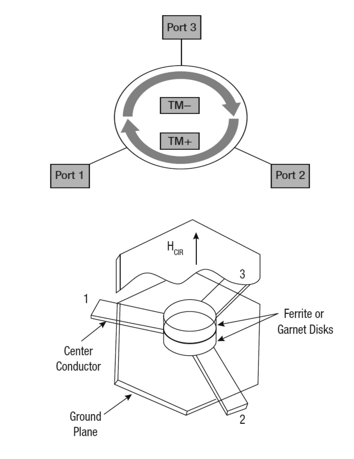
Figure 3. Schematic of circulator operations. Credit: From Skyworks RF Ceramics App Note 202840B – Use of ferrimagnetic material in circulators
For 5G materials, the nature of the circulator will need to change to accommodate operation at higher frequencies. For the 3–6 GHz band, the higher frequency would require changes to the design of the circulator, but not drastic changes to the ferrite materials used in the device. The industry standard circulator ferrite materials are based on yttrium iron garnet (Y3Fe5O12). Substituent elements such as calcium and zirconium are frequently added to improve the magnetic losses of the material and thus improve the insertion loss of the circulator device. Nonetheless, standard garnet structured ferrite materials have dielectric constant values between 12 and 15.
However, there is a class of materials developed at Skyworks that have dielectric constant values up to 31. This enhanced dielectric constant for these ferrite materials enables miniaturization of the circulator to make it more suitable for use in smaller base stations. The increased dielectric constant is due to the use of bismuth as a substituent ion for yttrium in the formulation. This material has the thermal stability of yttrium iron garnet, with a slightly higher saturation magnetization and much higher dielectric constant values. The magnetic loss can be decreased by the substitution of zirconium and therefore Y3-x-yBixCayFe5-yZryO12 is a state-of-the-art ferrite product branded by Skyworks as TTHiE-1950.4,5
For mm-wave circulators, the architecture and the materials used will be different from those used in 4G and previous systems. For one, the triplate designs will no longer be used and microstrip (below 20 GHz) or substrate integrated waveguide (SIW) based circulators will be needed. At these frequencies the magnetic material would need to have as high a saturation magnetization as possible so that the lower loss garnet ferrites could be replaced by high magnetization nickel zinc ferrite based spinels.
One technology battle that may occur in mm-wave technology would be between circulators and high-power gallium nitride (GaN) based switches. For 5G technology, particularly in the mm-wave space, duplexing rather than diplexing technology is likely to be used. For TDD (half-duplexing), some type of device will need to be used to switch between the transmit function and the receive function. The switch is a logical choice but may be subject to high insertion loss at these frequencies. However, a circulator may be used as well for this application. In addition, a switch would be unable to be used for full duplexing whereas a circulator would be able to readily handle full duplexing. With the abundance of spectrum available in the mm-wave space, full duplexing is not likely to be necessary for some time and therefore it would likely be considerations of loss and heating dictating whether switches or circulators will be used. As the mm-wave technology is likely to be the “wild west” for some time, one technology may dominate for a time only to be quickly supplanted by a different technology.
Solving processing challenges
Moving back to ceramics, it is worth mentioning a “shrink-wrap” or cofiring technology used to create sintered, monolithic composites of magnetic and dielectric oxide materials. This effort started at Skyworks when problems with intermodulation distortion (IMD) occurred. As stated earlier, magnets are applied to a ferrite disk to saturate the ferrite and bring about the directional (nonreciprocal) effect. However, if the magnet is the same diameter as the ferrite, it may be difficult to completely saturate the far edge of the ferrite disk, leading to IMD issues. This problem was initially solved by gluing a dielectric ring to the outer edge of the ferrite disk so that the diameter of the permanent magnet is greater than the diameter of the ferrite. In this manner, the outer edge of the ferrite disk is completely saturated by the permanent magnet. However, there are some difficulties with the use of polymer-based adhesives, including high dielectric losses and the inability to deposit metal over the glue bond. As a result of this, the “cofiring” process was developed.6 In this case (See Figure 4), a ferrite rod is sintered close to theoretical density. After firing, the ferrite is placed in a cylinder of unfired dielectric and the dielectric is sintered around the ferrite so that it “shrink-wraps” onto the ferrite to form a cosintered composite. The composite rod is then sliced into disks and each disk is used for an individual isolator. These composite disks contain no glue line and can be readily metallized.
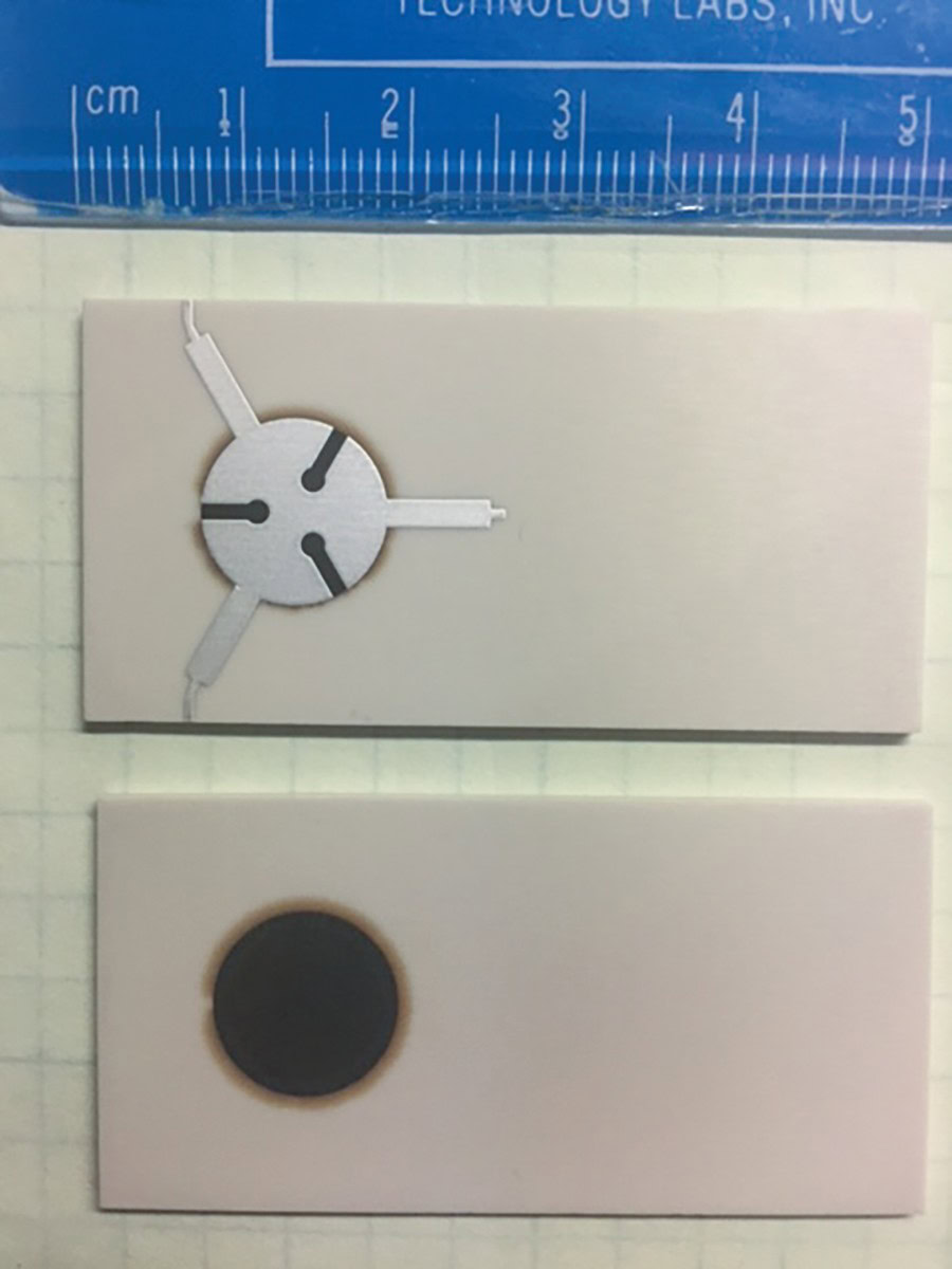
Figure 4. Representation of cofire process to produce ferromagnetic dielectric composites. Credit: D. Firor Skyworks RF Ceramics
There are a number of challenges inherent in this cofiring process. These include
- the dielectric must fire at a lower temperature than the ferrite rod,
- lossy phases should not form at the magnetic–dielectric interface,
- the thermal expansion coefficients of the two materials must match, and
- firing shrinkages need to be carefully controlled.
As a result, there is a limited suite of materials that are mutually compatible for this ceramic “shrink-wrap” process. In addition, there is a need for materials with a range of dielectric constants to accommodate different frequency values. This “shrink-wrap” process sets a limit on the number of ferrite materials that need to be developed because frequency selection can be done by varying the dielectric constant of the nonmagnetic dielectric ring.
One likely direction for 5G technology is the integration of various functional components into a module. This can be done readily with polymeric platforms or even planar LTCC materials. Our direction is to take the “cofiring” process a step further and integrate multiple components on a ceramic substrate. The core of the device is a microstrip circulator with the ferrite cofired onto a microwave dielectric material. This material can be LTCC based or a tailored material with a higher dielectric constant than most currently available LTCC materials (which rarely have dielectric constants greater than 10). This ceramic substrate may allow for surface mounting of additional devices, including low noise amplifiers and GaN power amplifiers (Figure 5), and may connect with antennas through vias in the ceramic substrate.7
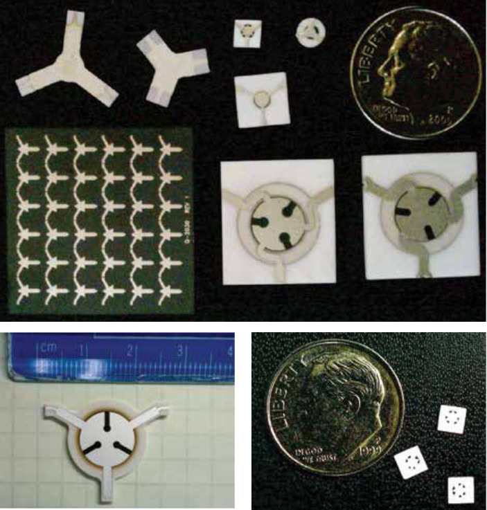
Figure 5. Photographs of integrated cofired mm-wave circulator devices. Credit: Courtesy of D. Firor, Iain Mac Farlane, and Dave Cruickshank (Skyworks RF Ceramics)
5G— An evolving network
In the mm-wave space, there may be a range of architectures used depending on the frequency of operations. Up to 20 GHz, microstrip circulators may be used. However, above 20–30 GHz, radiative losses become significant so microstrip circulators become untenable. Therefore, for these higher frequencies, substrate integrated waveguide-based circulators are needed, ones where the circulator is surrounded by a metallized “cage” to prevent radiative losses.7
The above is an overview on what we at Skyworks envision as likely components in 5G technology. While there are considerable technical challenges with regard to operating in the lower frequency band of 3–6 GHz, much of the technology would consist of higher frequency variants of current 4G technology. It is certain that systems will be deployed in this frequency range within a year or two—some have already been deployed at various frequencies. In this range, we would expect to see magnetic oxide circulators, some microwave dielectrics in base station filters, as well as ceramics in polymer ceramic composites (such as titanium oxide). For mm-wave space, the technical challenges are certain to be much greater; therefore, there will be several years before these systems are deployed. It remains to be seen what type of materials will be used in antennas and substrates although an educated guess would include both polymer- and ceramic-based systems (with ceramic based systems favored for higher power application in which waste heat management is an issue.) Additionally, there is a question of which duplexing technology will dominate in the mm-wave space, whether it be GaN switches or ceramic ferrite-based substrate integrated waveguide based circulators. In addition, there are semiconductor-based circulator technologies being developed, which may be better solutions than the biased ferrite technologies widely used below 10 GHz. In short, there will likely be a rapid evolution of different technologies over a short timeframe. However, with the large area of spectrum available and the projected demand, 5G technology will become critical for the global information age infrastructure.
Capsule summary
5G to the rescue
Compared to current 4G technologies, 5G communication offers higher data rates, low latency, and increased connectivity.
Materials for 5G
Compared to polymeric materials, ceramics provide a wider range of dielectric constants, better mechanical stability in thin sections, and the relative ease of metallization.
5G’s ‘wild west’
Early versions of 5G will be high frequency variations of 4G technology. However, it will take several years to solve technical challenges and fully realize networks operating in mm-wave frequencies.


Related Articles
Bulletin Features
The nonferrous metals market: Supply and regulatory pressures inspire strategies for a resilient future
Nonferrous metals serve foundational roles in the electrification, renewable energy, and digital transformation. Nonferrous metals are metals that do not contain iron in significant amounts. These metals typically are nonmagnetic, corrosion resistant, electrically and thermally conductive, and lightweight, making them ideal for applications in the emerging markets mentioned above. Even…

Market Insights
Industrial digitalization: ‘Smart’ operations can improve worker safety and well-being in high-temperature environments
Heavy industry is the backbone of economies around the world, critical to automotive production, construction, the energy sector, and everything in between. But many heavy industries are facing worker shortages. There are more than 400,000 open manufacturing jobs in the United States, according to the Bureau of Labor Statistics.1 With…

Market Insights
‘Fail fast’ manufacturing: How disciplined experimentation strengthens, not threatens, quality
In manufacturing, few phrases raise eyebrows faster than “fail fast.” In the startup world, this business strategy is celebrated as a sign of agility. On a ceramic manufacturing floor, it can sound careless or even dangerous. In manufacturing, few phrases raise eyebrows faster than “fail fast.” In the startup world,…