
A new epoch in high-temperature ceramic-matrix composites (CMCs) is upon us. Following three decades of research and billions of dollars of investment, CMCs are slated to appear in hot components in gas turbine engines for civilian aircraft.1,2 Their use is motivated by their low density, high strength and toughness, and, in some cases, higher-temperature capability relative to nickel-based superalloys.
As one example, all-oxide CMCs—typically alumina fibers in porous alumina/aluminosilicate matrices—will be used in engine exhaust structures. Composites Horizons (Covina, Calif.) has begun manufacturing mixer and center body assemblies from an oxide CMC for use in engines for long-range business jets that will be going into service later this year.2 Elsewhere, working with COI Ceramics (San Diego, Calif.), Boeing (Chicago, Ill.) has flight-tested an engine equipped with an oxide CMC exhaust center-body and nozzle on a 787 aircraft.3 At 2.3 m in height and 1.1 m in diameter, the center-body is the largest oxide CMC component ever made. The drivers for replacing metallic alloys with oxide CMCs in these applications include reduced weight, enhanced acoustic attenuation, and increased component lifetime.4
Much greater payoffs will come from insertion of SiC/SiC composites into the hottest parts of the engine—the combustor and turbine. In comparison with corresponding properties of superalloys, SiC/SiC composites have about one-third the mass density and 100K–200K higher upper use temperatures. This enables elevated operating temperatures—and, hence, improvements in thermal efficiency—and reductions in cooling air, thereby increasing bypass air and propulsive efficiency as well as reducing NOx emissions.
The first large-scale use of SiC/SiC will be in high-pressure turbine shrouds of CFM LEAP engines, which will enter service in June 2016.2 Similar materials will be used for inner and outer combustor liners as well as high-pressure turbine nozzles and shrouds in the GE9X engine, projected to enter service in 2020. SiC/SiC turbine blades may be introduced soon thereafter. SiC/SiC blades would produce much lower centrifugal forces and enable lighter turbine disks and bearings.
Despite the optimistic outlook, significant technical challenges remain for CMCs. Challenges fall into two broad categories:
- Design and optimization of composite microstructures to improve performance and durability; and
- Predictive tools that realistically capture the material performance envelope.
A primer on SiC/SiC processing routes
Prior to introduction of a matrix, SiC fibers are coated by chemical vapor deposition (CVD) with BN and a protective layer of either SiC or Si3N4. The matrix then is created by one or more of four processing routes (Figure 1).
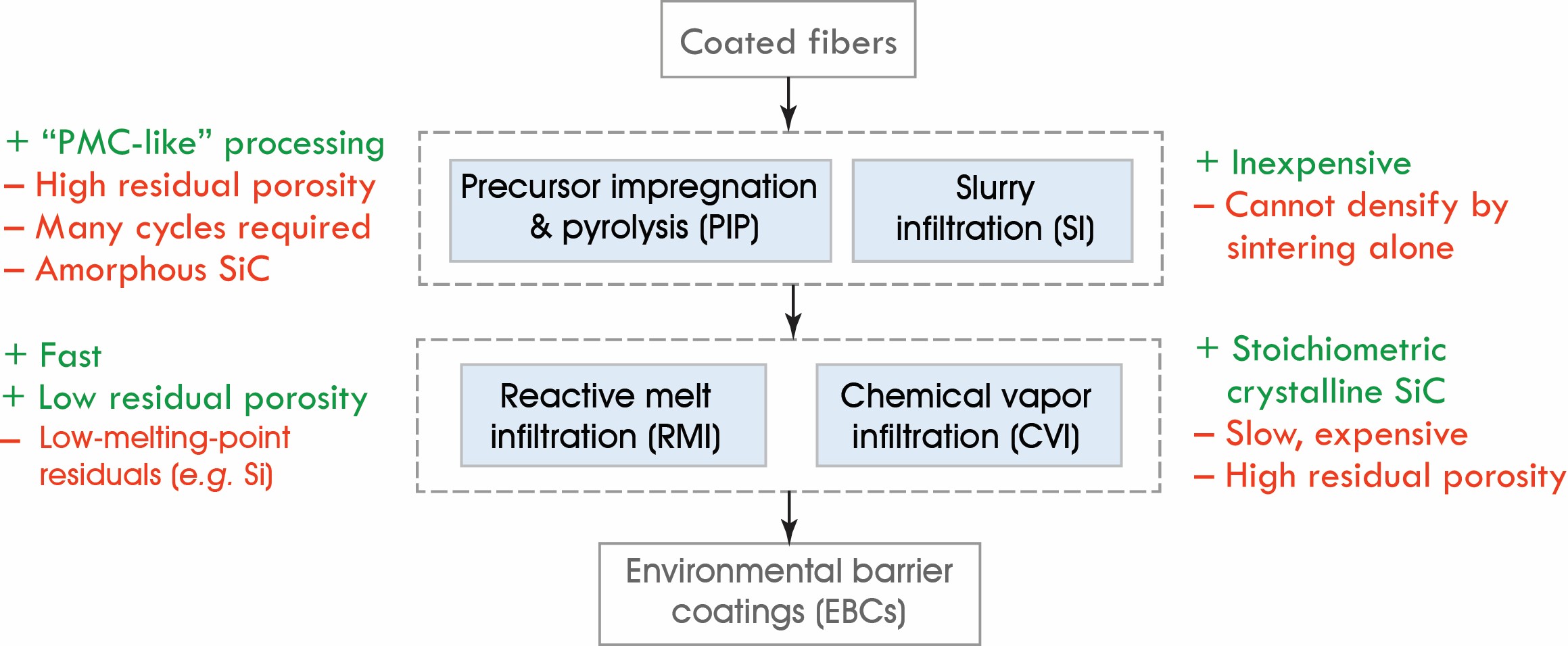
Figure 1. Pros and cons of various routes for producing SiC/SiC composites. Credit: Frank Zok
The first route involves chemical vapor infiltration (CVI). Although the porosity around fibers remains open and gases can access fiber surfaces, the process yields fully dense, crystalline SiC with high thermal conductivity and high creep resistance. Sealing of the external surfaces can be delayed through the use of low deposition rates and pressure and temperature gradients.5 However, even under the best circumstances, residual porosity is 10%–15%. Because of this porosity, the composites exhibit low through-thickness conductivity and low interlaminar strength.
The second route provides infiltration of particle slurries into dry fiber preforms via immersion or pressure-assisted routes that produce green preforms with particle packing densities of 30%–60%. However, because of physical constraints imposed by the (already dense) fibers, matrix densification cannot be achieved by sintering alone. For practical implementation, this route is combined with one involving precursor-derived ceramics or melt infiltration (described below).
In the third route, SiC-based matrices commonly are formed through repeated precursor infiltration and pyrolysis (PIP).6 Because of the mass loss and changes in mass density that accompany pyrolysis, volumetric yields are typically 20%–30%. In one variant, fine (submicrometer) SiC particles are added to a precursor on the first cycle to increase effective yield. In practice, terminal porosity is ≥10%. Additionally, the heterogeneous nature of precursor decomposition leads to microstructures with coarse (~100 µm) pores in the matrix-rich inter-tow regions, drying “mud cracks,” and fine-scale porosity.
Although open pores and cracks can be partially filled during subsequent PIP cycles, the resulting material remains friable and contributes little to matrix strength. An additional deficiency of PIP processes is that the matrices usually remain partially amorphous. Complete crystallization generally requires heat treatment at temperatures that exceed those at which most fibers are processed (e.g., 1,400°C–1,600°C). Such temperature excursions would cause significant loss in fiber strength. With amorphous matrices, composites exhibit very low through-thickness thermal conductivity.
The fourth route, reactive melt infiltration (RMI), has emerged as the preferred processing route for SiC/SiC composites. In its most successful implementation, the process begins with CVD of BN/SiC coatings onto tows of SiC fibers (not woven fabric), incorporation of SiC and carbon particles and a polymer binder via wet drum winding to produce unidirectional prepreg tapes, lay-up and autoclave consolidation of the tapes in the desired geometric configuration, binder burnout, and, finally, infiltration of molten silicon.7 Silicon reacts with carbon to form SiC. Although in principle the mixture of matrix particles can be designed to consume all silicon in the formation of SiC, some free silicon invariably remains.
Because infiltration temperatures are high (1,400ºC–1,500°C), the RMI process, too, can be used only with fibers that have been processed at comparable or higher temperatures. The process is rapid and yields matrices with minimal porosity. In turn, composites exhibit high thermal conductivity in-plane and through-thickness, high interlaminar strength, and high in-plane matrix cracking stress. However, their upper use temperature is limited by the low melting point (1,400°C) and low creep resistance of silicon.
The RMI process is used presently to manufacture SiC/SiC turbine shrouds. Similar processes will be used to produce other hot-engine components, including combustor liners, turbine vanes, and turbine blades.
Materials challenges that lie ahead
Current state-of-the-art SiC/SiC composites likely will satisfy the requirements for engine components at temperatures up to ~1,250°C. Their forthcoming use in moderately loaded components, such as shrouds, will undoubtedly yield valuable experience for engine OEMs (original equipment manufacturers). Even with this experience, the most ambitious goals—including use of CMCs in rotating components at temperatures up to 1,500°C—will require improvements in fibers, matrices, and fiber coatings. Properties that require attention and broad microstructural design goals are illustrated in Figure 2.
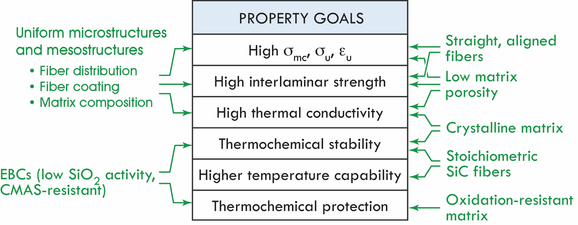
Figure 2. Microstructural goals for achieving property improvements. Here σmc is matrix crack stress, σu is ultimate tensile strength, and εu is tensile failure strain. Credit: Frank Zok
The targeted microstructural changes are based on established physical and mechanical principles. For instance, matrices should have minimal porosity and consist of high-conductivity (crystalline) phases for the through-thickness composite conductivity to be high. Low porosity also leads to high in-plane and interlaminar strengths as well as improved protection of fibers from the environment. Straight fibers (such as those within laminates) are preferred over wavy fibers (those within weaves), because waviness leads to stress elevations that exacerbate matrix cracking. Fibers should be stoichiometric to achieve high-temperature stability and retain high strength after exposure at elevated temperatures. Matrices should comprise refractory phases with temperature capabilities comparable to those of the fibers.
Quest for microstructural uniformity
CMC performance is dictated by intrinsic properties of the constituent phases and by the degree of microstructural uniformity. For example, laminates with uniformly separated fibers invariably outperform composites with 2-D fiber weaves. Differences derive from several sources, all based fundamentally on the degree of microstructural uniformity.
First, producing uniform coatings on fiber surfaces within woven fabrics is virtually impossible because of fiber–fiber contacts. Contacts prevent deposition of fiber coatings and allow fibers to sinter to one another locally during processing or in service. Even when total fiber surface area bonded to neighboring fibers appears small, the contiguity of bonded fibers can lead to highly correlated fiber fractures. Strength then is controlled largely by the very weakest fibers in the population.
Second, tight packing of fibers within a woven fabric coupled with inherently poor meshing of tows between adjacent fabric layers leads to matrix pockets with widely differing sizes. Within the tows, available spaces are about 5–10 µm in size, and access to those spaces is restricted by narrow (submicrometer) gaps between neighboring fibers. In contrast, matrix pockets between adjacent layers may measure hundreds of micrometers. When the size distribution is wide and access to some spaces is restricted, uniform and complete infiltration of matrix material by any of the aforementioned routes becomes problematic.
Even when access to available pockets is not severely restricted—as may be the case when a polymer precursor is infiltrated with pressure—nonuniformity of the flow front can lead to entrapment of pores. Further, anecdotal evidence suggests that precursor migration during depressurization (after infiltration) and outgassing and pyrolysis during subsequent heat treatment lead to nonuniform distributions in the resulting matrix product, including development of large pores.
Microstructural nonuniformities also exacerbate challenges in RMI processing. For complete filling and conversion of molten silicon into SiC, channels for melt ingress should be of uniform size, and the sources of active species (carbon) should be uniformly distributed and readily accessible by the melt. Otherwise, if molten silicon cannot gain access to carbon, free silicon will remain upon completion of the process. Channel size also must be large enough to allow ingress of the melt without reaction products “choking” the flow paths, yet small enough to ensure that the desired reactions proceed to completion within a reasonable time period.
Expanding the temperature envelope
Strategies for elevating composite use temperature focus on improved matrices. In one strategy, researchers are pursing alternatives to pure silicon for RMI. These involve alloys of silicon and refractory elements that have low eutectic points (to enable infiltration at lower temperatures) and that form high-melting-point silicides.
On another front, researchers also are pursing approaches for accelerating crystallization of precursor-derived SiC matrices. Although crystallization can be initiated at temperatures as low as 1,300°C, oxygen and excess carbon (both commonly present in precursor-derived SiC) hinder completion. Full crystallization requires removal of the latter elements by suitable heat treatment. Following crystallization, further processing via RMI or CVI could be used to further densify the matrix and enhance resistance to gas ingress.
The scourge of steam
Steam—an inevitable byproduct of hydrocarbon combustion—is particularly problematic for SiC/SiC composites. The problem involves reaction of water vapor with silicon-containing compounds to form gaseous hydroxide species. If left unimpeded, the reaction leads to global recession of SiC/SiC components. Steam also can lead to internal oxidation, which can be highly localized and difficult to detect externally.
Global SiC recession rates are sensitive to temperature, pressure, and velocity of the gas stream. For representative operating conditions—1,300°C, 10 atm water vapor, and 100 m/s gas velocity—the recession rate of SiC is about 0.5 mm/1,000 h.8 This rate of material loss is unacceptably high for engine components with expected lifetimes of many thousands of hours. The problem can be mitigated using environmental barrier coatings (EBCs) on CMC components. EBCs typically comprise rare-earth silicates that have thermal expansion coefficients comparable to that of SiC and that have an intrinsically low silica activity compared with the native silica scale formed on SiC.8
One of the most critical unresolved issues in the durability of SiC/SiC composites pertains to internal oxidation and embrittlement in steam-laden environments.9,10 Numerous thermochemical processes have been observed (Figure 3), including consumption of BN through formation of low-melting-point borosilicate glasses and subsequent formation of borohydroxide gases; replacement of BN by silica, which bonds well to fibers and the matrix and prevents crack deflection in interfacial regions; and reactions with free carbon (when present) within the fibers that lead to strength degradation and subcritical crack growth. These mechanisms appear to be most deleterious at intermediate temperatures (700°C–900°C).
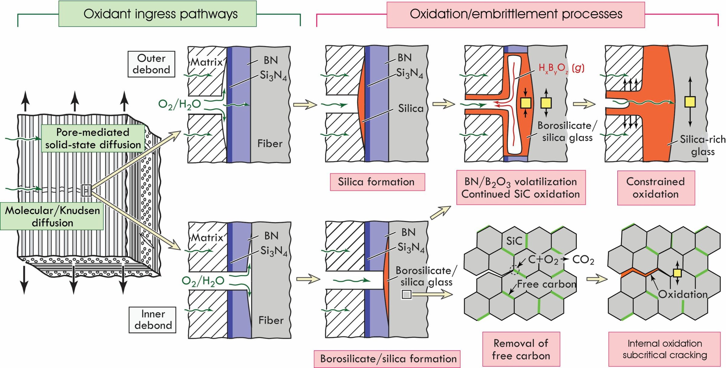
Figure 3. Pathways of oxidant ingress and internal reactions that lead to strength degradation and embrittlement of SiC/SiC composites with BN-fiber coatings. Credit: Frank Zok
An example of the manifestation of these mechanisms on fracture surfaces of a precursor-derived SiC/SiC composite is shown in Figure 4. Under monotonic tensile loading at ambient or elevated temperatures, surfaces exhibit extensive fiber pullout (reflecting the stochastic nature of fiber fracture) and small fracture mirrors (reflecting high fiber strength). In contrast, under stress rupture conditions in water vapor at 800°C, surfaces are mostly flat and fracture mirrors frequently encompass almost the entire fiber cross section. Localized removal of BN and formation of a glassy phase at the interface also are evident. Robust materials solutions to these phenomena have yet to be devised.
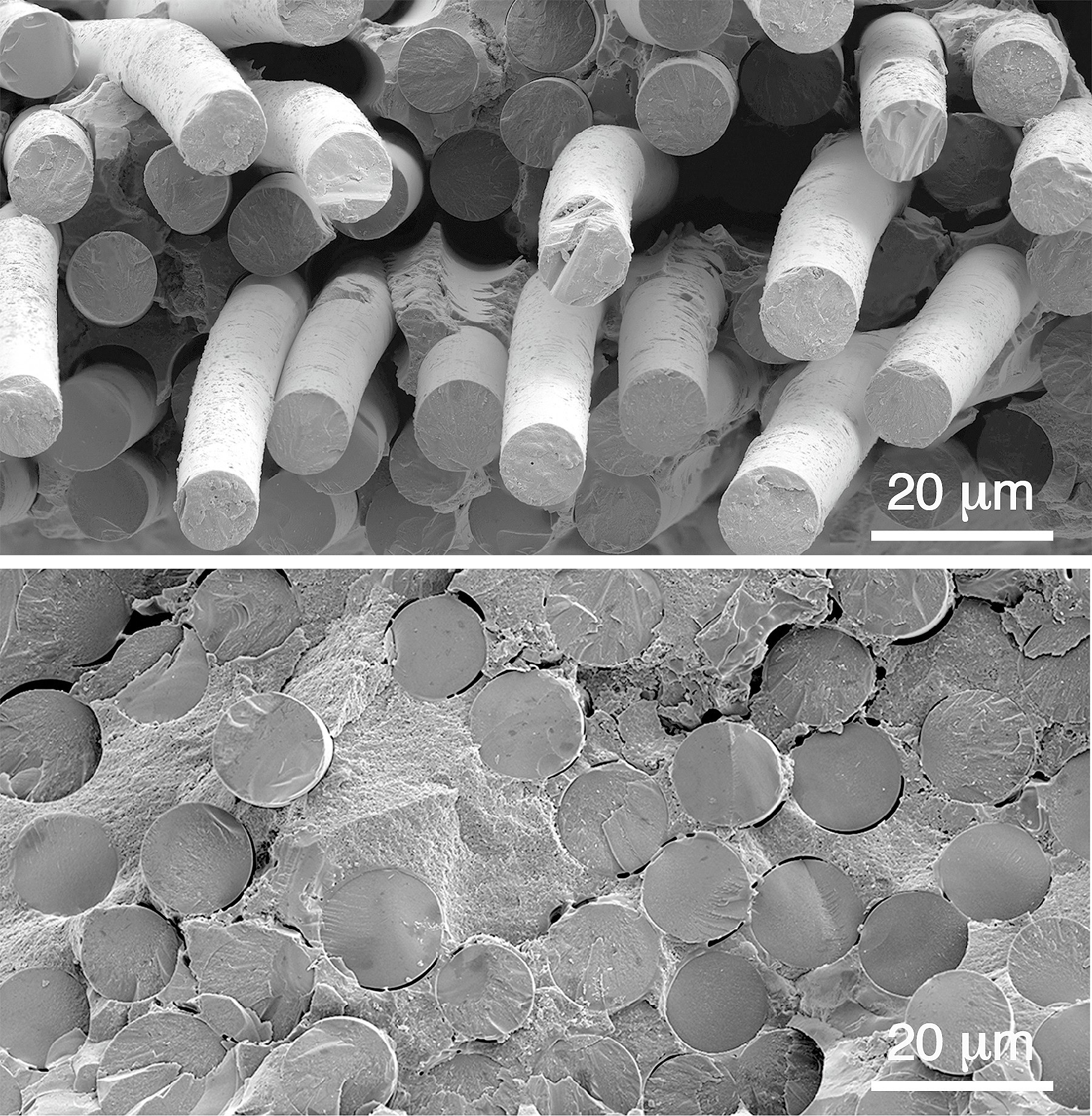
Figure 4. Fracture surfaces of a SiC/SiC composite tested under monotonic tensile loading (top) and under static loading at about one-half of the ultimate tensile strength at 800°C in water vapor (bottom). Credit: M.N. Rossol
Dust, ash, and sand
Siliceous debris commonly ingested into turbine engines can produce molten deposits of calcium magnesium aluminosilicate (CMAS) glass on components in the flow path. CMAS reacts with candidate EBC materials to form nonprotective phases.11 CMAS and reaction products readily crack upon cooling because of mismatch in thermal expansion coefficients. This can lead to spallation under cyclic loading conditions.
Proposed strategies for mitigating CMAS attack while maintaining resistance to recession from water vapor are based on multilayered coating designs. In one concept, the system comprises:12
- A silicon bond coat on the CMC, for adhesion of subsequent layers and for formation of a thermally grown oxide that inhibits inward oxygen diffusion and, therefore, minimizes oxidation of the SiC and attendant formation of CO gas;
- A coefficient of thermal expansion (CTE)-matched rare-earth disilicate layer (e.g., Y2Si2O7 or Yb2Si2O7) with low silica activity to serve as the primary barrier to water-vapor ingress;
- A layer of monosilicate of the same rare earth (YSi2O5 or YbSi2O5), sufficiently thin to limit thermal stresses, to further reduce silica volatility and serve as a diffusion barrier; and
- A CMAS-barrier layer, selected to promote rapid reaction and crystallization of the melt, thereby producing a barrier to further reaction or penetration of the melt (candidate materials include rare-earth zirconates, hafnates, titanates, and aluminates, each with attendant tradeoffs between performance and durability in a multilayer configuration).
The collection of layers must be designed to ensure thermochemical compatibility between layers and to mitigate stresses resulting from thermal expansion mismatch. In cases where a large thermal expansion mismatch exists relative to SiC/SiC (as is the case with all materials except disilicates of smaller rare earths), a low-compliance (segmented or porous) microstructure may be required to impart strain tolerance. Additionally, for CMCs that are expected to operate at the highest target temperatures (1,500°C), alternatives to silicon as a bond coat material will have to be devised. In principle, if new paradigms in matrix and coating architectures that strictly control oxidation of SiC were to be devised, the bond coat could be eliminated altogether. Solution pathways remain the subject of active research.
Realizing the potential of the material performance envelope
In practice, benefits derived from insertion of a new material are inextricably linked to level of understanding and degree of confidence in the material performance envelope. When the performance envelope is poorly understood, large safety factors on design stresses, allowable temperatures, and component lifetimes must be used. Reductions in safety factors translate directly into realizable performance improvements. These developments are predicated on predictive models of the performance envelope.
One of the principal damage mechanisms operating in SiC/SiC composites involves matrix microcracking, accompanied by interfacial debonding and fiber–matrix sliding. In addition to producing inelastic strain and degrading composite stiffness and thermal conductivity, microcracks compromise the efficacy of the matrix in protecting fibers and fiber coatings from the gaseous environment. Prediction of the degree of cracking and its effect on properties and durability is, therefore, crucial.
Established approaches to modeling inelastic and fracture properties of CMCs can be distinguished on the basis of length scales associated with the phenomena of interest and complexity of fiber architectures, structural geometries, and loading states (Figure 5, top row). For example, micromechanics-based models of matrix cracking and fiber fragmentation in laminates under simple loadings—e.g., uniaxial tension parallel to one of the fiber directions—are mature. Recently, these approaches have been extended to predict matrix cracking under multiaxial stress states and have been used to construct damage initiation surfaces (Figure 5, bottom left).13 Models of this type provide insights into the roles of constituent properties in composite response. In the present example, the model reveals a strong sensitivity of shear matrix cracking stress to the matrix modulus—a potentially tailorable property.
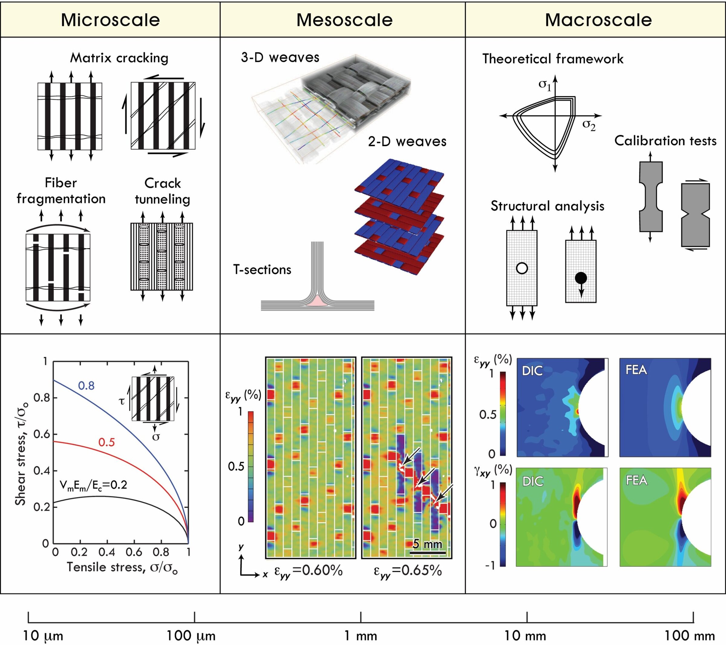
Figure 5. (top row) Approaches to modeling mechanical properties of CMCs. (bottom row) Examples of models and experimental measurements used for calibrating or assessing models and simulations. (left to right) Effects of matrix modulus Em on the combination of shear and normal stresses, τ and σo, for cracking (Vm, Ec, and σo represent matrix volume fraction, axial composite modulus, and tensile steady-state cracking stress, respectively);13 influence of fiber weave on distribution of axial strain εyy and on correlated tow rupture (indicated by arrows);15 and comparisons between local shear and normal strain fields in an open-hole tensile coupon, from digital image correlation (DIC) measurements and FE simulations.14 The latter demonstrate capability of the model in predicting magnitude and spatial extent of inelastic deformation under multiaxial stress states and in the presence of stress gradients. Credit: Frank Zok
For more complex structural geometries and stress states, models that encompass all of the pertinent physics are usually intractable or require extensive computational resources. In such cases, insights can be gleaned from models that capture the increased complexity in geometry and loading but concurrently increase the degree of approximation of constituent response. For example, if the goal is to predict macroscopic stress–strain response of a CMC under multiaxial loading over length scales that exceed the unit-cell dimensions, stress–strain relations of the homogenized medium can be described using phenomenological plasticity-like models, calibrated by a few standard mechanical tests. Models of this type have proved useful in predicting inelastic strain fields in open-hole tensile coupons (Figure 5, bottom right).14
When strain fields in woven CMCs are mapped at higher magnification, periodic strain patterns that reflect the underlying weave become evident. In CMCs with satin weave architectures, strains are greatest at the locations of tow crossovers on surface plies. More importantly, because of stress elevations in the axial tows between these strain concentration sites, fiber bundle rupture preferentially initiates in these regions. Once one tow ruptures, attendant stress elevations lead to a cascade of additional tow ruptures (Figure 5, bottom center). Finite-element (FE) simulations in which the tows are explicitly represented have been used to identify locations and magnitudes of stress elevations caused by the fiber weave and the ensuing strength debit.15 Such simulations also highlight the importance of matrix stiffness and strength in suppressing these stress elevations.
At intermediate length scales—between those defining a tow or a ply and those of the unit cell of the weave—and when structural dimensions approach the scale of the material microstructure, different modeling approaches are required. At the simplest level, each tow is represented by a contiguous set of 1-D line elements that are assigned properties that reflect axial tow properties. In turn, line elements are embedded within 3-D effective medium elements that embody all properties not assigned to the line elements.
Greater fidelity can be obtained through higher-order representation of the constituents. In one formulation, surface elements containing rebar layers are embedded within those 3-D elements that reside inside the tows. Effective medium properties are calibrated iteratively through comparisons of FE results with corresponding experimental measurements. Even-higher-fidelity results for damage prediction are obtained by tracking initiation and growth of individual matrix cracks using cohesive zone models. This approach is computationally most intensive and requires a high degree of computational expertise to generate and extract meaningful results.16
Determining the realizable performance envelope of a CMC component also requires explicit account of the efficacy and durability of EBCs. EBCs can develop a multitude of damage modes, including channeling cracks (normal to the coating surface), cracks that kink or bifurcate at or near layer interfaces, delamination cracks, and, in extreme cases, wholesale spallation. These damage modes can result from thermal transients (including thermal shock, gradients, and cycling) and can be exacerbated by stochastic events (e.g., ballistic impact) or concurrent environmental degradation (e.g., steam reactions or CMAS interactions). The phenomena are further complicated by fine-scale microstructural features that reflect the processing history of coatings. Such features can include oddly shaped pores, splat boundaries, multiphase constituents, and columnar grains.
Prediction of cracking in these systems remains a significant challenge. One approach is to use experimental observations of crack patterns to guide FE simulations of energy release rates and mode mixities and to use these results to identify conditions under which a specific cracking mode might develop. Alternatively, a more fundamental approach that incorporates cohesive traction between elements and allows explicit tracking of cracks could be used. In principle, the coating system could be modified accordingly—through selection of materials with different elastic moduli, CTEs, and toughnesses—to avoid a particular cracking mode. But this approach is heavily constrained by the few materials that satisfy thermochemical requirements. Alternative approaches in which coating architecture is used in conjunction with a small set of constituent materials may prove to be more effective. This, too, is an area of active research.
Acknowledgments
The author gratefully acknowledges financial support for research on ceramic composites from the U.S. Office of Naval Research (Grant No. N00014-13-1-0860), Pratt & Whitney, and United Technologies Research Center as well as helpful comments on the manuscript from N.M. Larson, D.L. Poerschke, T.E. Steyer, and D.M. Lipkin.
Capsule summary
Past
The superior properties of ceramic-matrix composites—including low density, high strength and toughness, and high-temperature capabilities—have put these materials in a position to replace superalloys in gas turbine engines in aircraft.
Present
Although ceramic-matrix composites are beginning to appear in service in gas turbine engines this year, even greater payoffs will come from insertion of composites into the hottest parts of the engine.
Future
Materials challenges lie ahead, but continued improvements in SiC/SiC composites and improved understanding of the material performance envelope will help realize the full potential of ceramic-matrix composites.

Related Articles

Bulletin Features
Emerging Professionals: Science for Society & Future Focus
One small tweak to the lens of materials research, one giant leap for mankind By Rishabh Kundu and Ryan C. Eaton One of the clearest existential threats facing humanity is anthropogenic climate change. The dire consequences to ecological stability and human prosperity if the status quo is maintained are thoroughly…

Bulletin Features
Emerging Professionals: Research Articles
Experiential learning: Developing the next generation of engineers By Ryan Eaton When a measure becomes a target, it ceases to be a good measure. Goodhart’s law, coined in reference to monetary policy, is readily applicable to engineering education. When students begin optimizing their study habits to pass an exam rather…

Bulletin Features
Durable and programmable metasurfaces enabled by phase change materials
Controlling light with high spatial precision enables technologies ranging from imaging and sensing to communications. Traditionally, optical components such as lenses and filters rely on bulk materials and fixed geometries, which limit their ability to adapt dynamically. Metasurfaces offer a fundamentally different approach. These materials consist of planar arrays of…