
After a slow rise to fame, the nanomanufacturing technique of electrospinning is gaining steam. The development of a high-throughput electrospinning setup at The Ohio State University opens the door to widespread use of this technique.
Since the turn of the 21st century, the field of nanomaterials has grown and gained prominence in numerous industrial sectors, including agriculture, pharmaceuticals, and chemicals processing. Yet even before these materials could be properly imaged and analyzed, people unwittingly employed nanomanufacturing techniques centuries beforehand.1
Of these techniques, electrospinning remains one of the most affordable and accessible approaches to nanofabrication. This technique produces submicron-diameter fibers and nonwoven mats via an electrostatic drawing process. It is primarily performed with polymeric materials, but it can also incorporate composites with ceramics or biomolecules.1
The electrospinning process was first patented by John Cooley in the early 1900s; however, initially there was little interest due to the low production rate and limited ability to characterize the fiber microstructures. Decades later, as advanced imaging and characterization methods were developed to analyze small-scale structures,2 interest in nanotechnology grew in the 1990s. Yet despite this increased interest, publications focused on electrospinning remained sparse for almost two more decades.
This article provides a brief overview of the electrospinning process followed by a summary of work on electrospun bioceramics and biomaterials for health-related applications. A discussion of high-throughput electrospinning (HTES) is presented along with the potential for its widespread adoption using a new device developed by ACerS Fellow Perena Gouma’s group at The Ohio State University (OSU).
The electrospinning process
The process of electrospinning, much like electrospraying, involves a polymeric solution that is electrically charged via an electrostatic field. This solution is pushed through an extruder and deposited on a collector, facilitating the formation of a material with desired micro- and nanoscale features.
The simplest setup includes a syringe extruder with a needle or other small-diameter conductive capillary tip. A precursor solution of polymer and solvent is loaded into the syringe, which is placed into a syringe pump to produce a slow, continuous flow, typically within the ranges of 0.5–2.5 mL/h. The positive lead of the power supply is connected to the needle tip and the ground is connected to the collector to create a static electric field.
As the solution droplet at the needle tip encounters the electric field, the positive electromagnetic force of the field pushes against the surface tension of the solution. The electromagnetic force causes the solution droplet to narrow and extend into a conical shape known as the Taylor cone. Once the repulsive force of the field overcomes the surface tension, the cone tip narrows into a jet that eventually splits into fine fibers that fly through the air and deposit onto the collector. A schematic and experimental image of the Taylor cone can be seen in Figure 1.3
Over this flight distance (also known as the working distance), the precursor solvent evaporates, leaving the dried polymer fibers to land on the collector. The grounded collector then dissipates the fibers’ charge, thus allowing for more fibers to deposit on top.
The resulting electrospun material is a nonwoven, flexible, and self-supporting mat of fibers that can be peeled from the collector for further processing or application (Figure 2). Depending on the collector used, different orientations of fibers can be obtained. For example, a standard flat plate collector yields randomly oriented fibers, whereas a spinning barrel drum collector yields aligned fibers. The geometry of the fibers can lend to different applications. For instance, randomly oriented fibers have advantages in filtration applications due to their low porosity and high surface area, while aligned fibers have advantages in mechanical applications due to their higher tensile strength.
Publications focused on electrospinning began appearing in greater numbers in the mid-2000s when the chemical fiber industry received increased focus and support. Since then, electrospinning has shown applications in filtration, photocatalysis for energy generation, and biomedicine, among others.4
Figure 1(a). (a) Schematic of the Taylor cone formation. The positive force of the electrostatic field helps form the droplet into the cone by pushing on the surface tension. Credit: (a) Tessa Gilmore
Figure 1(b). (b) A Taylor cone during an electrospinning experiment.3 Note how the cone extends for a small length before finally splitting into fibers (circled). Credit: (b) Gilmore and Gouma, Scientific Reports (CC BY-NC-ND 4.0)
Figure 2. An electrospun nonwoven mat of polyvinylpyrrolidone (PVP) fibers. The fibers were collected on a flat plate and therefore are randomly oriented. Credit: Tessa Gilmore
Electrospinning opportunities in health-related applications
Gouma’s group at OSU has been at the forefront of this resurged interest in electrospinning (see sidebar: “Perena Gouma: Leading the way in ceramic electrospinning at The Ohio State University”). They have demonstrated several innovations and applications for electrospun bioceramics and biomaterials, starting with the development of enzyme-containing electrospun fibers for biosensing applications in 2005.5
In medicine, a higher amount of urea in the human body can indicate kidney and liver function issues. So, researchers need a way to determine how much urea is in the body. The urease E.C.3.5.1.5. enzyme is a catalyst in the hydrolysis of urea to ammonia and carbon dioxide. By using urease to measure the amount of ammonia in the hydrolysis reaction, a relationship can be postulated to predict the amount of urea that is present.
As described in the 2005 publication,5 Gouma’s group electrospun a fibrous mat comprised of polyvinylpyrrolidone (PVP) and urease. It was the first time that a phosphate buffer solution (PBS) and ethanol were used for electrospinning enzymes. The electrospun receptor mat displayed rapid response times with the ability to detect ammonia at the trace concentrations needed for clinical applications. It also demonstrated a preservation of enzyme functionality for several months post-processing.
By showing this preservation of functionality, Gouma’s research opened up the avenue for other research groups to use the PBS+ethanol method for electrospinning proteins, such as collagen.6 As a result, the Collegiate Inventor’s Competition recognized this electrospun receptor as a breakthrough in biosensors based on nanotechnology. Today, this enzyme encapsulation method is important in preserving synthetic proteins for transfer and use.
Electrospinning has other applications in biosensing and health diagnostics, such as the use of blend electrospinning with sol-gels to synthesize metal oxide nanowires for gas sensing. This sol-gel-based electrospinning method involves a variation on the traditional electrospinning process: Instead of a purely polymer precursor, with particles possibly dispersed within the matrix, a sol-gel precursor is used along with an amenable polymer carrier. Generally, a metal salt and carrier polymer are dissolved in a common volatile solvent. After electrospinning, each fiber consists of the sol encased within the polymer. Subsequent calcination in a furnace burns off the polymer and leaves nanowires of the desired metal oxide.
In 2006, Gouma’s group successfully employed this sol-gel method to synthesize single crystal molybdenum trioxide (MoO3) nanowires for ammonia (NH3) gas sensing probes.7 NH3 is released through the breath and skin in small quantities and is an important biomarker in health monitoring because it relates to internal organ function. The goal in obtaining single crystals was to reduce the instability caused by the grain boundaries in multigranular oxides usually employed in gas sensing. The single crystal MoO3 nanowires displayed a sensitivity to NH3 much higher than that of the polycrystalline sol-gel-based MoO3 films stabilized under the same conditions. Specifically, the single crystal MoO3 displayed a sensitivity that scaled with the aspect ratio of the nanowires.
This experiment demonstrated that electrospinning not only could be used to create single crystal nanowires, but it also showed that these nanowires had an extremely high sensitivity to gases and the potential for use in breath analysis devices. Additionally, the group used this method to synthesize tungsten oxide nanowires for nitrogen dioxide gas sensing. These wires also displayed an improved gas sensitivity and response time when compared to tungsten oxide sol-gel films.8 Ultimately, this nanotechnology has enabled the miniaturization of artificial olfactory devices for noninvasive medical diagnostics.
Also in 2006, Gouma’s group demonstrated the use of electrospinning for tissue scaffolding by processing 3D scaffolds that mimicked the topology of the extracellular matrix (ECM) of a porcine unary bladder.9 The ECM is a 3D structure system in the body that provides attachment points and mechanical support for cell growth. The ECM from the porcine small intestine or urinary bladder is especially suitable for regenerating tissues such as vena cava, small-diameter arterial grafts, and urinary bladder.
The electrospun mat consisted of cellulose acetate (CA), which is a biopolymer capable of imitating the biofunctions of the ECM. The mat also incorporated a dense layer, a cellular layer, and a fibrous layer on top of one another to imitate a natural ECM. The experiment illustrated that electrospinning as a single technique could be used to control both the architecture and the chemistry of a bioscaffold and that these scaffolds could be made using a single-step process with minimal required patterning.
Similarly, in collaboration with biotechnology colleagues, Gouma’s group used electrospinning to create a thin, porous membrane of CA for scaffolds demonstrating microvascular cell growth.10 Here, precursor solutions of CA with various concentrations of added carbon nanotubes were electrospun into fibrous mats. Endothelial cells then were trypsin digested, deposited onto the mats, and left to mature over several days. The results indicated that all electrospun mats, including the control mat with no carbon nanotubes, could support the cells and demonstrated live cells after maturing five days. Additionally, following the initial deposition, cells appeared to spread across fibers to later form tubular-like structures (Figure 3).
Figure 3. Fluorescence microscope image of endothelial cells growing on CA + carbon nanotube membranes. Green indicates live cells (marked by white arrows).10 (a) Cells after initial seeding. (b) Cells after five days of maturing; note the tubular structures formed along the fiber. Republished with permission Credit: Han et al., MRS Online Proceedings Library

Figure 4. Scanning electron microscopy images of growth on electrospun mat.11 (a) Osteoblast cells grown on CA and n-HA composite fibers. (b) New apatite mineral crystallites grown on composite fibers; the circled crystallite most clearly shows the hexagonal structure. Republished with permission. Credit: Gouma et al., Materials Science and Engineering: C
The carbon nanotubes originally were added to provide more structural stability to the CA fibers for the cell growth, but they were found to be unnecessary. The CA mat with 0% w/v carbon nanotubes displayed the same cell viability as the CA mat with 0.25% w/v carbon nanotubes and a higher cell viability than the CA mat with 0.5% w/v carbon nanotubes.
Building on this research, in 2012, Gouma’s group illustrated the successful growth of bone cells via a CA and nanohydroxyapatite (n-HA) electrospun composite.11 Hydroxyapatite is the major mineral of natural bone and thus lends itself well to the synthesis of artificial scaffolds for bone repair. Previous efforts by other researchers revealed that ceramic–polymer composite systems suffered from poor dispersion and agglomeration of the ceramic powder when attempting to make artificial scaffolding. However, the employment of nanotechnology, and specifically electrospinning, helped to overcome these barriers.
The experiment performed by Gouma’s group included an electrospun CA and n-HA composite mat. The mat then was seeded with osteoblasts (i.e., cells that grow bone tissue) and left to mature for up to 14 days. After maturity, the seeded osteoblasts were observed to have used the electrospun fibers as anchoring points, and that allowed new apatite minerals to form on the fibers (Figure 4).11 Ultimately, the research showed that electrospinning is a promising candidate in the synthesis of bone scaffolds for repair and growth.
In recent years, many other groups have employed electrospinning for biomedical advances. For example, in 2023, Zhang et al. published a review detailing how the random mesh and high porosity of electrospun mats can facilitate the healing of wounds.12 Not only can the fibers act as anchor points for cell attachment and growth, but they also can prevent excess water loss and maintain a moist environment for the wound as well as prevent bacteria from entering the wound.
Additionally, electrospun fibers can be made from natural or synthetic polymers and can be loaded with additives for antibacterial or growth properties. For example, Chen et al. electrospun a mat of polyurethane with kaolinite and silver nanoparticles.13 The mat demonstrated the ability to reduce inflammation and promote collagen deposition to accelerate healing.
Along with wound healing, electrospun mats are being investigated as hemostatic bandages for acute hemorrhage. Many hemostatic cloths and powders employ clays to promote clotting and stop excess bleeding. In 2021, Cui et al. exhibited a mat of PVP fibers loaded with kaolinite clay to suppress massive bleeding.14 The mat displayed an improved performance on hemostatic time and effect compared to other commercial products. These mats can be a promising tool for prehospital care and may contribute to saving many lives in military conflicts, traffic accidents, and surgical procedures.
Another major application of biomedical electrospinning is for use in drug delivery. The electrospinning process offers a large amount of customization and tunability that is not available in other nanofiber synthesis processes. The produced nanofibers also are well equipped for the sustained and controlled release mechanisms required in drug release materials.
While research in this application is nascent, many review articles have been published explaining the opportunities that electrospinning offers for drug delivery systems. Once such article by Gaydhane et al. thoroughly explains the different drug delivery systems in the human body and how electrospun fibers may perform in each of them.15
High-throughput electrospinning
With the many applications and advancements discussed here, one may ask why electrospinning is not more ubiquitous. The main challenge lies with scalability. Conventional lab-scale electrospinning is a very slow process that only fabricates about 0.01–0.1 grams of fibers per hour, which is too slow for industrial-scale performance.
Over the years, several groups have proposed different geometries to increase the fabrication rates of electrospinning. Two popular geometries are multineedle16,17 and open reservoir.18,19 While these geometries have shown large increases in fabrication rate, they suffer from yield loss issues detrimental to industrial upscaling.
Regarding multineedle setups, they can exacerbate needle clogging issues seen in conventional single-needle setups. These setups also can suffer from jet-to-jet interactions. Because most geometries call for single electric potentials, electrospun jets positioned too closely can repel one another and impede fibers from depositing onto the collector.
On the other hand, open-reservoir setups, including bowl-edge and bubble setups, employ large open surfaces of the precursor. This open pool can lead to premature drying of the solvent and requires the top layer of the precursor fluid to be repeatedly removed, substantially reducing the fiber production rate. These open reservoirs also can pose a health hazard due to the volume of solvent evaporating and the frequent use of toxic solvents employed in electrospinning.
A handful of companies, such as Elmarco (Liberec, Czechia) and Fluidnatek (Paterna, Spain), have designed very large machines capable of industrial-scale processing. However, these devices are restrictive in terms of usable polymers and solvents, which limits the capability of these machines given new electrospinning innovations. Additionally, these machines have an extremely large footprint, sometimes needing their own dedicated room, and can cost millions of dollars.
Ideally, an electrospinning setup would allow for multiple jets of fibers without risk of clogging or inter-jet interactions and could support the large quantity of an open-reservoir setup without the solvent prematurely evaporating. Such a system was designed in 2014 by Gouma’s group (Figure 5).3,20 This system employed a hollow disk extruder placed within a surrounding drum collector. The hollow disk had 24 short-distance capillary holes around the circumference. When fed with a continuous supply of precursor and electrical charges, the disk produced Taylor cones at all 24 capillary holes for fiber formation. The setup is similar to the bowl-edge geometry developed by Thoppey,18 but it overcomes the issues of inter-jet interactions and premature solvent evaporation. The 24 capillary holes are carefully spaced to allow for the maximum amount of Taylor cones without overlap and the enclosed disk keeps the precursor from drying out.
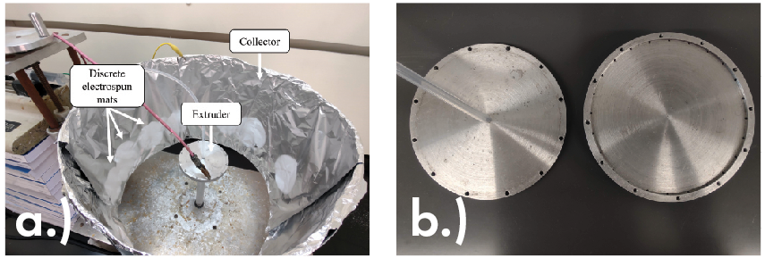
Figure 5. High-throughput electrospinning (HTES) prototype developed by Sood and Gouma in Reference 20. Pictures from Reference 3. (a) HTES prototype extruder and collector electrospinning discrete mats of fibers. b) The top half (left) and bottom half (right) of a hollow disk extruder. The 12 larger holes on top are for screws to attach the two halves. The capillary holes can be seen along the inside ridge of the bottom half. Credit: Gilmore and Gouma, Scientific Reports(CC BY-NC-ND 4.0)

Figure 6. Improved high-throughput electrospinning setup built by The Edward Orton Jr. Ceramic Foundation.3 (a) Main parts of the electrospinning setup. (b) A continuous fibrous mat electrospun by the system. The white tray at the bottom simply acts as a drip tray. Credit: Gilmore and Gouma, Scientific Reports (CC BY-NC-ND 4.0)
Initially, this system solely consisted of the novel collector and extruder, with the power and fluid pump supplied through external sources. Additionally, the system would create discrete circular mats that could eventually overlap only if enough precursor was electrospun. Regardless, the system provided a solid proof of concept that left room for growth.
Upon receiving an Accelerator Award from the state of Ohio in 2022, Gouma’s group worked with The Edward Orton Jr. Ceramic Foundation to design and fabricate a second iteration that became the first proper and self-contained prototype apparatus (Figure 6).3 This new system incorporates a power supply and fluid pump, which allows it to be self-contained, and a reasonably small footprint, which allows it to sit on top of a lab bench or within a large fume hood. The latter feature mitigates the need for the installation of dedicated HVAC hookups. The fluid pump also provides for more flexibility in the precursor amounts without being constrained by syringe size, unlike the previously used syringe pump.
Possibly the most impactful addition to the new design is the connection of the collector drum to a small motor, which allows for the collector to slowly rotate during electrospinning. This rotation is critical as it permits the electrospun mat to be a continuous rectangle rather than the separated circles made by the original system, as seen in Figure 6b. Once removed from the collector, the electrospun mat has dimensions of about 36 cm x 119 cm (1.18 ft x 3.90 ft).
The new design supports a fabrication rate that is roughly 15 times greater than that of a conventional, single-needle setup. As such, this current apparatus is ideal for lab-scale high-throughput electrospinning, but the geometry of the setup is also geared to act as a bridge to industrial-level production rates. This extension can be made by enlarging the collector and extruder disk, which would provide for more capillary holes, thereby permitting more jets and a greater rate of fibers per hour on a larger surface area collector. The simplicity of the system also means that a variety of solvents and precursors can be used, unlike the more restrictive industrial-scale machines offered today.
More information about this high-throughput electrospinning apparatus can be found at https://mse.osu.edu/acrl.
Summary
Since the mid-2000s, electrospinning has demonstrated great potential in many biomedical applications, including tissue and bone repair, wound healing, drug delivery, and gas sensing, as well as other health-related fields. Publications focused on electrospinning are growing in number each year as the scientific community finds new innovations and applications for these beneficial mats.
The rapid advancement and growing number of these applications shows an increased imperative for scaled-up electrospinning machinery to promote commercial viability. Various research groups have demonstrated feasible setup constructs. However, many of these proposed setups exhibit design flaws, such as exacerbated clogging or premature solvent evaporation. A few companies have fabricated large machines capable of industrial-scale production, but they also suffer from limited workable solvent and materials, which restricts scientific innovation.
The high-throughput electrospinning system developed by Gouma and her research group is a key advancement in electrospinning technology for biomedical and other applications because it allows for faster lab-scale electrospinning and offers a clear gateway to industrial-scale fabrication rates. The flexibility of the system also provides an avenue to commercial viability for the many inventions listed here. Improvements in high-throughput electrospinning apparatuses may lead to the increased adoption of this versatile processing technique and further innovations in biomedicine and healthcare in the future.
Read more: “Perena Gouma: Leading the way in ceramic electrospinning at The Ohio State University“
Read more: “Electrospinning for environmental remediation applications“

Related Articles

Bulletin Features
Emerging Professionals: Science for Society & Future Focus
Science for Society articles: Rishabh Kundu and Ryan C. Eaton: “One small tweak to the lens of materials research, one giant leap for mankind” Grace Dunham: “Microwave firing: Inspiring young scientists through rapid ceramic demos” Hossein Libre: “Shaping materials science through policy engagement” Future Focus articles: Kartik Nemani: “Hope and…

Bulletin Features
Emerging Professionals: Research Articles
Experiential learning: Developing the next generation of engineers By Ryan Eaton When a measure becomes a target, it ceases to be a good measure. Goodhart’s law, coined in reference to monetary policy, is readily applicable to engineering education. When students begin optimizing their study habits to pass an exam rather…

Bulletin Features
Durable and programmable metasurfaces enabled by phase change materials
Controlling light with high spatial precision enables technologies ranging from imaging and sensing to communications. Traditionally, optical components such as lenses and filters rely on bulk materials and fixed geometries, which limit their ability to adapt dynamically. Metasurfaces offer a fundamentally different approach. These materials consist of planar arrays of…