The black-and-white image of an X-ray is no stranger to most of us. It is used extensively in medical applications to identify changes to bones, such as decalcification and arthritis, and in failures, such as chips and breaks. But medicine is not the only application of radiography—readily available X-ray imaging methods,1 with their ability to reveal information not visible on the surface of an object, can offer insights into materials composition and processing methods as well.
The use of X-rays in the field of cultural heritage were popularized by Alan Burroughs, who traveled through Europe for Harvard’s Fogg Museum with a portable X-ray instrument to image firmly attributed paintings and develop an understanding of the working methods of artists.2 Unlike the film-based methods used by Burroughs, most X-rays are now made using digital techniques. This article focuses on 2D X-ray methods, in particular computed radiography, which is a common successor to film-based methods due to the similarity in both use of the flexible image plate to film and the resultant resolution as well as its increased ease of use. 3D methods, not discussed here, were discussed in volume 93, issue 7 of the ACerS Bulletin (September 2014).
From cradle to cradle: Steps in the production process of ceramics
In the 1960s, the term chaîne opératoire was coined in French lithic studies3 to describe the steps involved in the life of a stone-based tool or object, from the sourcing of raw materials to its production, use, and eventual disposal. In defining a technology using this model, each step is examined from its place in creating the object but also from the point of view of the society that produced it. In other words, the constraints and choices by the maker can be placed in the greater context of workshop organization and the role of craft specialists, extending out toward the place of the technology in society and the interactions with the local environment.
This methodology of investigation now is used in studies of archaeological ceramics as well. For unglazed ceramics, the first step in the model is the sourcing of necessary clays, temper, and other additives. This step is followed by material preparation, including preparation of clay and mixing it with temper; forming methods, such as slab building or coiling; decorative methods, such as slip application, burnishing, or painting; and then firing. The production is followed by the use life of the object, its disposal, and then rebirth in its second “cradle,” i.e., its use in the museum to inform and educate.
When studying materials from archaeological sites, information from geological surveys combined with environmental surveys at the sites provides information on local material sources. However, museum objects generally lack the context available for scientifically excavated archaeological objects, and so information on raw materials is not available. In addition, we often have little first-hand knowledge or textual information on the materials and methods used to make cultural heritage objects. We rely on reverse engineering the objects themselves to understand the technological choices that were made in their manufacture. In these cases, the object is the primary evidence for the technology and, often for ancient technologies, the only evidence.
X-ray radiography is a useful method for examining the fabric of ceramics, providing information on the materials used and the ability to rapidly survey a collection of objects. Radiography is especially useful when the ceramics are slipped, burnished, or glazed and the body itself is not visible.
An example of X-ray radiography’s usefulness is in investigating temper. Temper, a nonplastic inclusion, is added to clay to reduce shrinkage during firing and/or change the properties of the fired ceramic during use. Temper shape and size distribution are visible in an X-ray radiograph as well as variations in temper type, which are determined by variations in radiodensity.
Mineral temper is visible as bright spots (it has higher radiodensity than the clay) in this sherd from a Ban Chiang culture ware (Figure 1).4 The Ban Chiang culture flourished in prehistoric Thailand and ceramics were produced at several sites. The computed radiograph tells the fabric of the upper part of the vessel, containing a higher amount of mineral temper, is different from the fabric of the lower body. While we can suggest the lower amount of temper and higher porosity in the lower body of the vessel may help prevent cracking due to thermal shock during use, from a single example such as this one it is not possible to say if it was done purposefully or simply because the potter ran out of his first batch of clay. The study of a single museum object provides limited data. More certain findings are only possible when examining the larger numbers available from an archaeological site. This approach, unfortunately, often is not possible with objects in museum collections, which generally lack this context.i
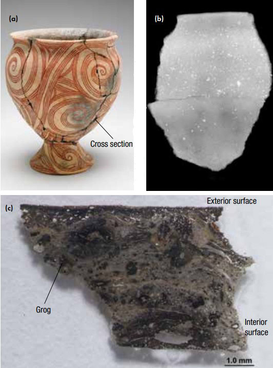
Figure 1. a) Vessel on pedestal foot, Late period 300 BCE–200 CE, Ban Chiang culture, northeast Thailand dimensions: H x Diam (overall): 30 x 27 cm Arthur M. Sackler Gallery, S2004.24. b) CR of sherd visible in (a); and c) Optical microscope image of polished thin section. Credit: (c) Conservation and Scientific Research, National Museum of Asian Art, Smithsonian Credit: (a) Arthur M. Sackler Gallery, Smithsonian Institution, Washington, D.C.: Gift of Victor and Takako Hauge, S2004.24 Credit: (a) Arthur M. Sackler Gallery, Smithsonian Institution, Washington, D.C.: Gift of Victor and Takako Hauge, S2004.24 Credit: (b) Conservation and Scientific Research, National Museum of Asian Art, Smithsonian
While it is not possible to identify the materials of the ceramic using this technique—unless you have a limited number of known materials composing an object and have carried out calibrations—it can help to identify locations for fruitful further studies. In this case, a sample spanning the wall of the ceramic was removed from the body and a thin section prepared for petrography and later scanning electron microscopy. The identified temper materials included grog (previously fired clay fragments) and minerals characteristic of sand (i.e., quartz, iron silicates, and zircon). In addition, the clay has high porosity with small amounts of added organics and a nonuniform clay matrix that suggests the clay(s) and other components were not well mixed, which is not surprising given the uneven distribution of temper seen in the CR.
Radiographic techniques also reveal information on forming methods used. For the Ban Chiang culture vessel, the observed variation in radiodensity (small undulating areas of lighter and darker grays, especially visible in the lower half) is consistent with the paddle and anvil method of shaping the clay used in southeast Asia, i.e., a method in which an anvil is held by the potter on the interior of the vessel and a paddle is pressed against it. (For a video including the technique, see https://youtu.be/fl9KbNYK6xY.)
People have studied forming methods of ancient ceramics since the 1970s using the technique of xeroradiography, a type of X-ray imaging, due to excellent edge definition between materials of similar radiodensity, low sensitivity to scattered X-rays, and its wide exposure latitude.5 In this technique, an electrically charged selenium coated aluminum plate is placed behind the object of interest and exposed to X-rays. Similar to other radiographic techniques, differences in X-ray absorption by the object define the amount of radiation reaching the plate. This difference in turn is proportional to loss of the negative charge, forming a latent image on the plate. Negatively charged powder particles are attracted to positively charged parts of the plate, then transferred to coated paper under heat and pressure.
The two ceramic bull drinking vessels called rhytons shown in Figure 2 are both burnished on the surface and xeroradiography was useful to examine them for differences in forming methods. Xeroradiography determined these vessels shared some construction techniques but varied in others. Both are multicomponent constructions with separate pieces used for the body, head, legs, vessel neck, and handle. Both are formed of coils (indicated by the thin white vertical lines in the sides of the vessels on the xeroradiograph). However, the hollow bodies of the bulls were closed differently, with S1987.94 (Figure 2a,b) closed at the front and S1987.95 (Figure 2c,d) at the rear. This difference is shown by the rougher interior wall and the mottled appearance that indicates greater manipulation of the clay in these areas.
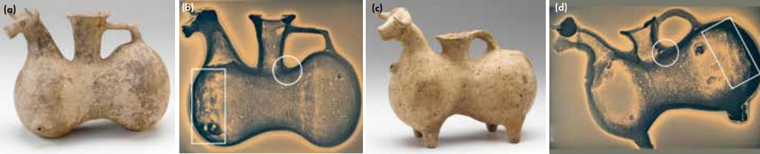
Figure 2. Zoomorphic rhytons (drinking vessel), Northwest Iran, Parthian period ca. 160 BCE–224 CE, and side-view xeroradiographs (acquisition conditions: 75 KV, 5 mA, 1 minute). Arthur M. Sackler Gallery. a,b) S1987.94 (H x W x D: 20.3 x 25.6 x 14.1 cm); and c,d) S1987.95 (H x W x D: 23 x 29.2 x 12.3 cm). Square around mottled area; circle around neck join. Credit: Arthur M. Sackler Gallery Smithsonian Institution, Washington, D.C.: Gift of Arthur M. Sackler, S1987.94 and S1987.95. Xeroradiographs taken at Smithsonian’s Museum Conservation Institute.
The join of the vessel neck to the bull’s body is very well finished, appearing as a continuous clay corner in S1987.94. The join is much less continuous in S1987.95, where the clay from the vessel neck sits over the clay from the bull’s back. This observation suggests that the first bull’s neck was attached before the body of the vessel was closed and the other was added after the body was closed when further finishing was not possible. The two handles both contain elongated pores coincident with their length, indicating the clay was pulled (if the clay had been rolled, but not pulled pores would either have a circular cross-section or show elongation across the handle), but they are attached differently—S1987.94 has one end of the handle attached to the vessel neck and the other to the wall of the body, while S1987.95 has a loop with both sides of the handle attached to the walls of the bull’s body (note the perception of greater thickness caused by the handle at the rear of the vessel neck relative to the front wall of the neck). Each of these small differences is a technological choice that the craftsman made and can be used together with other elements of the production process to define cultural groupings. In addition, by comparing the xeroradiographs with the shape of the object, it is possible to use the knowledge gained to aid interpretation on other zoomorphic vessels when X-ray imaging is not available. In this case, the side that is closed by hand is not as evenly rounded as the other side.
Xeroradiography was once popular for mammography due to its wide exposure latitude and edge enhancement that made it possible to image over an area of varying thickness while resolving features that varied little from the matrix, but it has been supplanted by digital radiography techniques. The technique is no longer readily available, with the last holdouts being instruments that individual labs have managed to keep running and in veterinary applications, in which short exposures made possible by the wide exposure range are an advantage. A more modern X-ray technique called computed radiography (CR) uses a standard X-ray tube as a source and a flexible phosphor image plate as the detector.ii After exposure, the plate is scanned, providing a born digital X-ray image.6 CR has more of the advantages of xeroradiography than film did with a large dynamic range allowing broad exposure latitude, but computed radiographs do not have the edge definition seen in xeroradiography.
Figure 3 shows an ancient near eastern tripod ewer and radiographic images of it. As can be seen in the xeroradiograph (Figure 3b), each leg is a separately formed vessel, and the three are joined at the center of the vessel. The join appears as a dark vertical line at the center and cannot be seen on the object itself. Elongated porosity at the tips of the legs as well as in the handle show that these areas were stretched. The xeroradiograph has a white halo effect that formed due to migration of the charged powder particles toward the charged edges of the image. One advantage of CR, as seen in Figure 3c, is that it lacks the halo. However, with CR, the details of the image are a bit washed out. Digital processing of computed radiographs sharpens the image and aids interpretation. A great advantage of CR over film-based methods is the ability to adjust brightness and contrast individually for areas of interest of different thickness to see the evidence of joins or of pores and inclusions in the fabric of the ceramic.
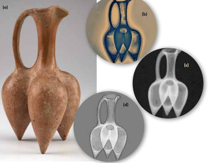
Figure 3. a) Tripod ewer, ca. 1350–800 BCE, Northwest Iran H x W x D: 21.6 x 11.5 x 12.2 cm (8 1/2 x 4 1/2 x 4 13/16 in) Arthur M. Sackler Gallery S1998.169. b) Xeroradiograph (55KV, 5mA, 60 seconds), image reversed for easy comparison. c) Computed radiograph. d) Computed radiograph after digital processing with Adobe photoshop (Adjust levels to expand channels used, filter: Find edges, adjust levels to expand channels used a second time). Credit: (a) Arthur M. Sackler Gallery, Smithsonian Institution, Washington, D.C.: Gift of Osborne and Gratia Hauge, S1998.169. (b) Xeroradiographs taken at Smithsonian’s Museum Conservation Institute. (c-d) Conservation and Scientific Research, National Museum of Asian Art, Smithsonian.
Unlike the bright smaller temper particles, the dark larger void is a cylindrical hole from sampling for thermoluminescence dating and is visible in the middle leg near the bottom (Figure 3c). Processing the image with edge filters and expanding it to make use of all channels increases the areas of differing thickness that are visible together and results in similar information to that possible with xeroradiography, as seen in Figure 3d. The rough edges of the interior profile and variations in the ceramic are most easily visible in this image. The high resolution of the CR plate, 50–100 micrometers or even higher, can surpass that of the xeroradiograph and, if the original X-ray was optimized (i.e., included use of lead screens and filters to minimize scatter and use of proper acquisition conditions), more information generally is present in the CR than the xeroradiograph.
Rethinking the technique of core-formed Egyptian glass vessels
Previous radiography on glass objects conducted in the laboratory is scant, as it is often true that most features visible in the X-radiograph can be seen through careful observation of the glass or through a microscope, thus making the use of a radiograph unnecessary. However, radiography can enable one to see bubbles in opaque or corroded glass, as well as providing information on vessel contents, interior shape, and wall cross-section. We also have used radiography as a survey technique to quickly group glasses of similar composition, discriminating between, for example, lead glasses and soda lime glasses on the basis of their radiodensity prior to sample selection for compositional and trace element analysis. The different brightness at the top (turquoise capital) and bottom (dark blue tube) of the broken and repaired core-formed Egyptian glass kohl tube in Figure 4 indicates two different glasses are present. This object, purchased by Charles Freer in 1909, is comprised of parts of two different objects. Sometimes a dealer or collector, when confronted by several small fragments, would assemble them to have one complete whole object, whether or not the pieces belonged together, forming a pastiche such as seen here.
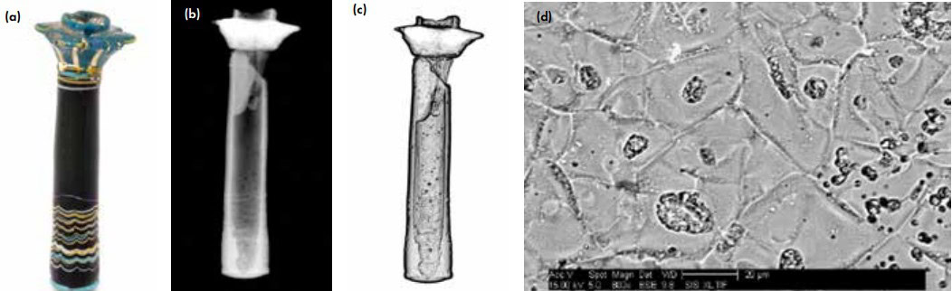
Figure 4. a) Flask in the form of Lotus column, New Kingdom Egypt ca. 1390–1300 BCE, H x W: 9.5 x 3.3 cm, Freer Gallery of Art, F1909.427. b) Computed radiograph, 55KV 2mA, 60 seconds, focal spot 1.9 mm. Adobe Photoshop “Find edges” filter applied and levels maximized using “Adjust levels.” c) Backscattered electron image of sample removed from turquoise capital. Credit: (a) Freer Gallery of Art, Smithsonian Institution, Washington, D.C.: Gift of Charles Lang Freer, F1909.427. (b-d) Conservation and Scientific Research, National Museum of Asian Art, Smithsonian.
In the study of this piece and other core-formed objects,7 CR provided support of a recent revision in understanding how these objects were made.8,9 Long thought to have been made by wrapping threads of glass around a clay core, Egyptian core-formed vessels are now believed to be made using sintered powdered glass with added wrapped glass threads for decoration. This significant revision was hypothesized due to the appearance of the objects, with bubbles scattered randomly throughout a uniform base glass. In this revised thinking, a preheated refractory core in the form of the interior of the vessel is coated with glass powder and the whole reheated to form the glass object.
Randomly scattered throughout the digitally processed CR of a lenticular core-formed vessel are bubbles of circular cross-section (Figure 5). The random location and great variation in size of the circular bubbles is consistent with a process involving application of a powdered glass to a core with subsequent heating step(s) to melt and merge the glass into a continuous piece. No striae or other differences in composition, as might be expected from wrapped threads used for the base glass, were seen in the radiographs. The CR gave an overall view of the nonuniform wall cross-section. This knowledge can be used to differentiate the core-formed vessel from one of blown glass, in which the surface tension results in a smooth uniform wall.
Figure 5. a) Light blue Lentoid flask, New Kingdom Egypt, ca. 1539–1295 BCE, H x W x D: 8.4 x 6.7 x 3.8 cm (3 5/16 x 2 5/8 x 1 1/2 in) Freer Gallery of Art, F1909.416. b) Computed radiograph, 55KV 2mA, 60 seconds, focal spot 1.9 mm. GE Rhythm Radiography “Enhance Edges” filter applied. Credit: (a) Freer Gallery of Art, Smithsonian Institution, Washington, D.C.: Gift of Charles Lang Freer, F1909.416. (b) Conservation and Scientific Research, National Museum of Asian Art, Smithsonian.
The use of powder was confirmed, at least for the capital of the kohl tube, by examination of a small sample. It exhibited a microstructure of angular sharp-edged grains that appear to preserve the shape of the original powder particles when examined with backscattered electron imaging. A sample taken from a replicate vesseliii made from crushed glass applied to a core also exhibited a microstructure of sintered glass particles under backscattered electron imaging. In both replications and ancient glass vessels, however, the glass particles generally were not visible as the glass fully melted during reheating.
Once the glass is heated, the softened glass is marvered or rolled on a flat, smooth surface to shape and smooth the vessel. Evidence of marvering is present in the kohl tube—it has an approximately 90 degree corner from the wall to the base on the exterior but exhibits more of a “U” shape on the interior. Walls are thinner at the upper edge of the capital, and other examples of this type of kohl tube provide evidence that glass in this area was pulled upward to form petals around the mouth of the container.
Decorative glass threads are added and are marvered to flatten the threads and secure them to the vessel. Additional glass may be used to form handles or decorative elements, and the core is removed when cool. As support for using glass powder, we know the ancient Egyptians used powder processing methods to make faience, a ground quartz-bodied ware.
Role of substructure in the response of East Asian lacquer to environmental changes
Chinese and Japanese lacquers are composed of a substructure that is commonly made of wood coated with multiple layers of modified lacquer formed from the sap of the tree Toxicodendrum verniciflua that, when cured, results in a polymeric material that is virtually insoluble even in modern solids. The lacquer layers vary in composition and contain additives such as minerals, oils, fibers, and colorants. Often a textile layer is applied over the wood substrate. Next, a foundation layer composed of clays and minerals bound with protein glue is applied to the wood support. After the foundation, a series of lacquer layers containing additives of increasing fineness are applied in succession with polishing steps between the lacquering steps to form a smooth, durable coated surface.
In a study of Japanese and Chinese lacquers, CR was used to image the wood substrate, determine the presence or absence of textile layers, and find the location of joins between pieces of wood in the substructure. These factors are key to understanding the behavior of a lacquer object when exposed to environmental changes and provide insights into the mechanisms of mechanical deterioration. One challenge was imaging the low radiodensity wood substrate when the overlying lacquer was colored by the higher density red pigment mercury sulfide or when there were decorative metal inlays. We had the best results in these cases by increasing the X-ray energy to approximately 200 KV and using lead filters at the X-ray source and lead screens before and after the image plate to absorb scatter. Joins seen in the bottoms and tops of boxes studied were generally parallel to the grain direction, as can be seen in the CR in Figure 6b, where the lid of a 17th century Chinese box is made from three pieces of radially cut (rift sawn) wood. This cut, radially outwards from the center to the exterior of the log, was chosen as it results in the most dimensionally stable piece of wood. Textiles were applied to the wood prior to the lacquer as an underlayer to provide stabilization.
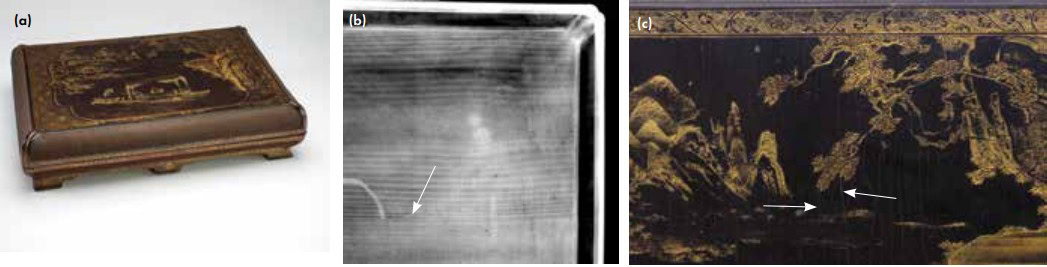
Figure 6. a) Rectangular box with basketry panels and painted design, Late Ming dynasty, probably Wanli reign, first half of the 17th century, H x W x D: 12.8 x 38.9 x 56.2 cm (5 1/16 x 15 5/16 x 22 1/8 in) Freer Gallery of Art F1956.4. b) Computed radiograph of side of lid. Arrow points to join; textile weave is visible as cross-hatching. c) Detail of lid, arrows point to cracks in the lacquer. Credit: (a) Freer Gallery of Art, Smithsonian Institution, Washington, D.C.: Purchase — Charles Lang Freer Endowment, F1956.4a-b. (b-c) Credit: Conservation and Scientific Research, National Museum of Asian Art, Smithsonian.
With changes in relative humidity, the wood substructure and lacquer layers exhibit different amounts of hygroscopic (moisture) expansion, setting up stresses that can cause cracking.10 In wood, moisture expansion is greater cross-grain than in the direction of the grain, which exhibits little to no change with changes in relative humidity.
At first glance with the wood constrained as part of the box, one might expect cracks to open in the cross-grain direction of greatest expansion. Yet cracks visible at the surface of the lid of the lacquer box shown in Figure 6c open perpendicular to this direction, suggesting that they did not form due to expansion of the wood. Lacquer also absorbs water and exhibits moisture expansion that must be considered. However, the directional dependence of the wood expansion relative to the isotropic behavior of lacquer is a clue that the wood is involved in formation of the unidirectional cracks.
Wood in the grain direction essentially remains fixed, not expanding or contracting with changes in moisture content. This fixation results in a greater difference in dimensional change between the wood and the coating (lacquer) layers in this direction and greater stress in the coating as compared to the cross-grain direction where the wood also expands and contracts. At some point in the history of the box, the strain in the coating in the grain direction was high enough to result in cracks (Figure 6c). However, the controlling material or layer for the failure cannot be determined without further knowledge. The lacquer box is composed of a complex multilayer composite, and understanding its behavior requires looking at all the lacquer layers and the specific additives in those layers that may affect the behavior of the aged lacquer and thus of the whole.11
Conclusion
Noninvasive radiographic techniques allow examination of the entire object and may be used both for initial surveys and for examination of processing techniques in greater depth. In addition to their utility in reverse engineering of processes, radiography reveals what is hidden under the surface. It aids in hunting for root causes in failure investigations. And, these techniques yield valuable information for a range of material types: polycrystalline, glassy, and mixed systems of materials. Commonly available, they are a useful addition to the analytical tool chest.
Acknowledgments
The Smithsonian’s Museum Conservation Institute provided access to xeroradiography equipment. Kerith Koss and Ellen Chase collaborated on work on ceramics and Pamela Vandiver and Laure Dussubieux on the Egyptian glass work. I am thankful to Rose Thun, Allison Davies, Glenn Gates, Tim Flaherty, Eileen De Guire, Glen Gaddy, Alison Murray, and Donna Strahan for helpful discussions.


Related Articles

Bulletin Features
The nonferrous metals market: Supply and regulatory pressures inspire strategies for a resilient future
Nonferrous metals serve foundational roles in the electrification, renewable energy, and digital transformation. Nonferrous metals are metals that do not contain iron in significant amounts. These metals typically are nonmagnetic, corrosion resistant, electrically and thermally conductive, and lightweight, making them ideal for applications in the emerging markets mentioned above. Even…

Market Insights
Industrial digitalization: ‘Smart’ operations can improve worker safety and well-being in high-temperature environments
Heavy industry is the backbone of economies around the world, critical to automotive production, construction, the energy sector, and everything in between. But many heavy industries are facing worker shortages. There are more than 400,000 open manufacturing jobs in the United States, according to the Bureau of Labor Statistics.1 With…

Market Insights
‘Fail fast’ manufacturing: How disciplined experimentation strengthens, not threatens, quality
In manufacturing, few phrases raise eyebrows faster than “fail fast.” In the startup world, this business strategy is celebrated as a sign of agility. On a ceramic manufacturing floor, it can sound careless or even dangerous. In manufacturing, few phrases raise eyebrows faster than “fail fast.” In the startup world,…