
Recreating the engine environment
Service conditions for materials used in extreme environments associated with propulsion, energy conversion, and hypersonic and space transport include high temperature and heat flux, elevated stresses, and oxidative and corrosive settings. Combining high-temperature alloys and ceramics in a substrate–coating system ensures load-bearing capacity of metal alloys through thermal insulation by the protective coating. Simultaneously, the coating provides oxidation and corrosion resistance in extreme operating environments.1 Such systems have enabled successful applications, such as thermal protection systems on launch vehicles, leading edges of hypersonic vehicles, and thermal barrier coatings on internally cooled turbine engine blades. Further, advances in these areas must address current limitations in performance, efficiency, and durability of coating systems.
Concurrent research in processing new ceramic compositions and coating deposition techniques provides an opportunity for methodical optimization of properties and parameters to push boundaries most efficiently. The question has been whether extensive modeling and simulation can substitute for materials inserted into demonstration engines.2 But is it possible to strike middle ground by recreating the extreme environment and, in the process, achieve one that is amenable to in situ measurements? The results from such an experiment would capture and compare material responses with time, temperature, and loading conditions and would provide these critical data to improve simulation models.
The extreme and dynamic operational environments ceramic materials are exposed to significantly influence their mechanical behavior and properties. These influences must be met head-on with high-resolution testing techniques to track all aspects of response under in situ conditions (Figure 1). But what critical and unique information could such tests reveal? Thermal barrier coatings (TBCs)—backed by more than 30 years of research and development into their behavior and failure mechanisms—are excellent candidates for such an in situ investigation. Beyond the capabilities of high-temperature alloys, these coatings increase the operational temperature of turbine components by about 100°C with direct impact on engine efficiency improvements.
High-temperature-coating candidate
TBCs are multilayered systems consisting of a low-thermal-conductivity ceramic top layer, bond coat and an interfacial layer between the two. The protective coating system is deposited on the high-temperature alloy turbine blade substrate. The first layer, the bond coat, is an oxidation-resistant metallic layer with high aluminum content, such as NiCoCrAlY or PtAl. The ceramic, typically yttria-stabilized zirconia (YSZ), is deposited over the bond coat. A thermally grown oxide (TGO), predominantly alumina, forms and grows at the interface between the YSZ and bond coat during engine operation. Bond coat and ceramic top coat can be applied by various coating techniques, most commonly electron beam vapor deposition (EB-PVD) and plasma spraying (PS). EB-PVD and PS yield significantly different coating microstructures, but both furnish the top coat with high porosity that imparts low thermal conductivity and high strain tolerance (Figure 2). The combination of bond coat and top coat layers protects the superalloy turbine blade substrates, allowing turbine inlet temperatures to reach about 1,600°C in aircraft engines. Over the long term, superalloy service temperatures are limited to 1,050°C. TBCs experience simultaneous thermal and externally applied mechanical strains, which induces degradation that controls TBC life (Figure 3).
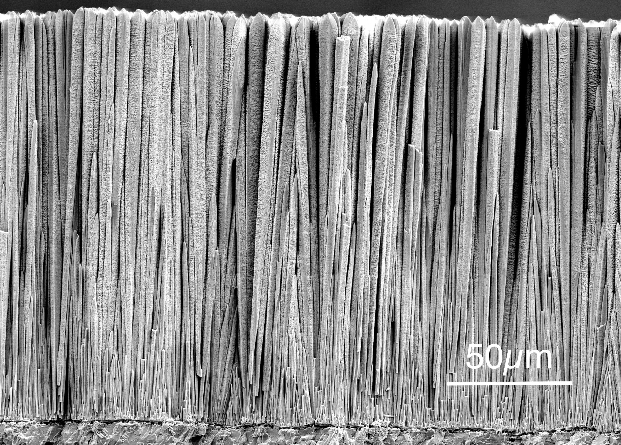
Figure 2. Microstructure of YSZ coating applied by EB-PVD. Credit: Uwe Schulz; DLR
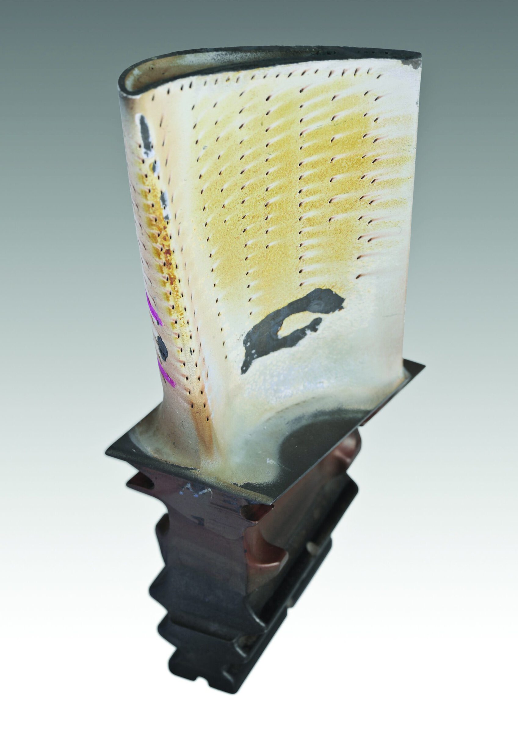
Figure 3. Thermal barrier coating damage on a turbine blade. Credit: DLR
Under operational conditions, critical strains caused by several factors develop within the oxide and are linked to the degradation and eventual spallation of the coating. Some sources of strain include thermal mismatch between layers (which manifests as evolving strains), changes during oxide formation, and stresses that evolve as growth of the TGO is constrained.3,4 Rumpling of the TGO manifests as undulations and is affected by growth/thickening rate, strain, and thermal expansion misfit with the substrate. In this sense, the mechanics of the oxide layer and its interfaces hold significant information with respect to failure mechanisms.
All these factors are time- and temperature-dependent with individual influences. Characterization after failure reflects a multitude of effects that cannot be separated easily.5 Therefore, a strong need exists to quantify these influences through in situ measurements under recreated and controlled environments. Recent literature shows growing efforts to raise testing capabilities to the next level.6,7
Determining creep, thermal expansion, and other properties of the material system in its native operational environment will provide critically needed data for accurate material behavior modeling of TBC response.
Test standards inspire technique
The German Aerospace Center (DLR) and Cleveland State University (CSU) researchers Bartsch and Karlsson have made significant experimental contributions to establish failure modes in TBCs under thermal gradient and mechanical loading conditions.8 They used these results to establish analytical and simulation models, respectively. The DLR Institute of Materials Research in Cologne developed a special test facility to analyze, on laboratory specimens, the effects of complex operating conditions experienced by a turbine blade and its protective coating during flight (Figure 4). Therefore, the degradation, damage evolution, and failure produced in these laboratory tests are expected to be realistic. Precise genesis of the damage observed can be explained only after local stress and strain profiles of a load cycle are known. However, no direct measurement of local strains in the coating system at high temperatures of about 1,000°C has been available at DLR.
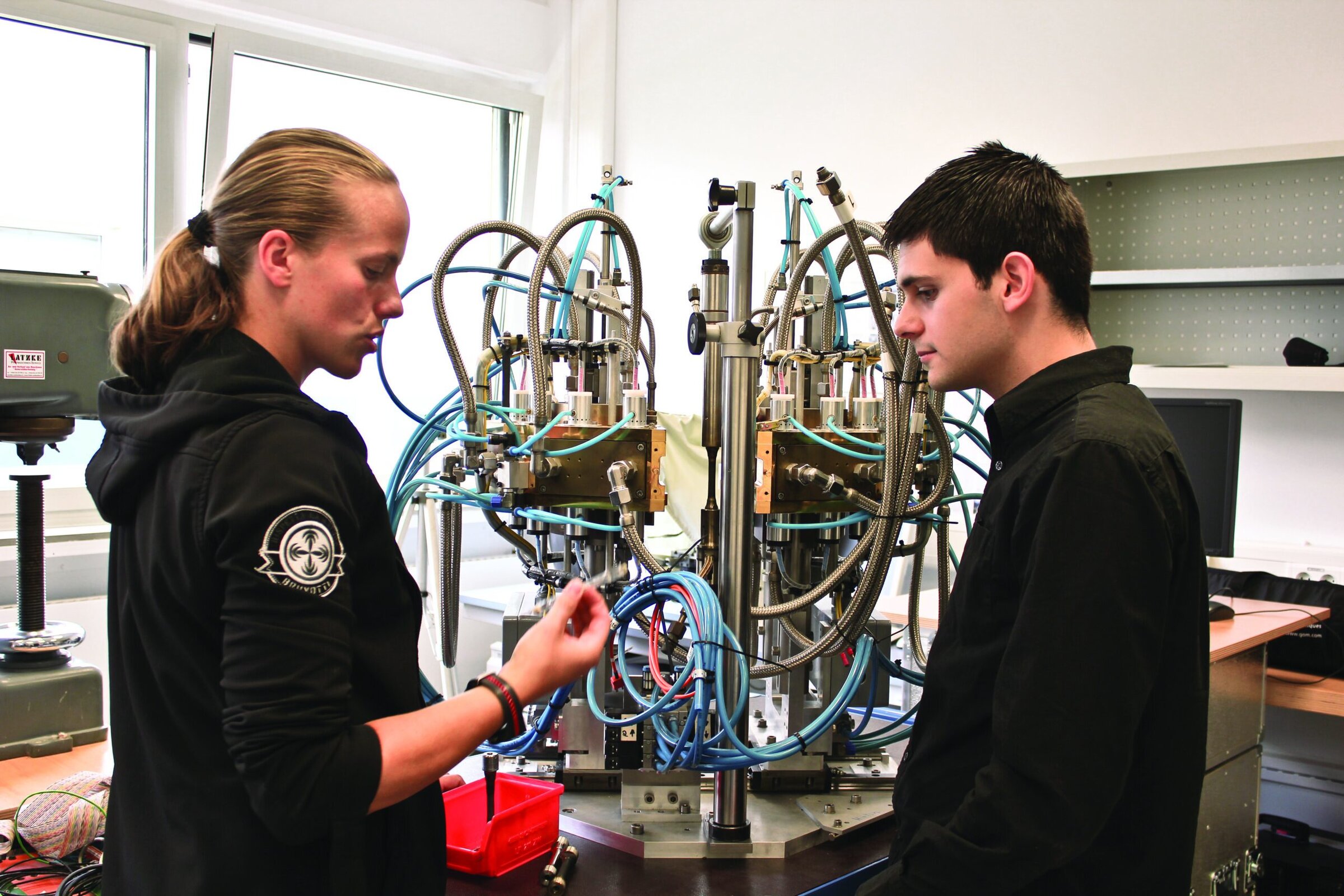
Figure 4. Janine Wischek explains the DLR thermal gradient test rig (shown) to Albert Manero during summer research at DLR. Credit: UCF, DLR
Collaboration between Bartsch and the Karlsson team, prompted by a meeting during the 27th International Conference on Advanced Ceramics and Composites (ICACC) in Cocoa Beach, Fla., has furthered progress. Using numerical simulations and corresponding validation experiments, the researchers found sound explanations for observed damage evolution9. Although the results are plausible, they depend on reasonable assumptions of materials properties because reliable property data for thin coating layers are lacking, especially at high temperatures.
The missing link
The 35th ICACC in January 2011 in Daytona Beach, Fla., brought another scientist into the conversation. Seetha Raghavan from the University of Central Florida (UCF) suggested the potential of the synchrotron source at Argonne National Laboratory (ANL) for characterizing the TBC system. Raghavan collaborates with ANL scientists Jonathan Almer and John Okasinski. Raghavan proposed designing and integrating a modified test facility at ANL, similar to the one at DLR. The high-energy X-rays emitted by the synchrotron would enable the team to penetrate the layers and observe interactions between radiation and material. The resulting X-ray diffraction patterns could be used to determine strain—and, further, stress—in individual layers. This was the missing link to validate calculations with direct measurements.
The effort required to recreate the complex engine environment has immediate merit when it comes with the promise of achieving in situ, high spatial, strain resolution measurements using synchrotron X-rays. Challenges to integrating this recreated environment with the synchrotron include designing innovative measurement techniques for complex samples and advanced instrumentation with access, as well as capturing high-resolution data in a dynamic environment.
Integrating synchrotron measurements
Strain-dependent characteristics of ceramics under the effect of light sources, such as high-energy X-rays, hold key information, which can potentially delineate the strain behavior that makes these coated systems superior, yet limits their durability. These noninvasive techniques transcend length scales, providing high-resolution measurements that target strain response of individual materials within the layered system. This is achievable only if highly brilliant X-rays—emitted from particles travelling close to the speed of the light in the 1,104-m circular storage ring—can be integrated somehow with loading and heating instrumentation that provides micrometer-scale motion of the sample with respect to the fixed beam, all while the sample is exposed to operational environments.
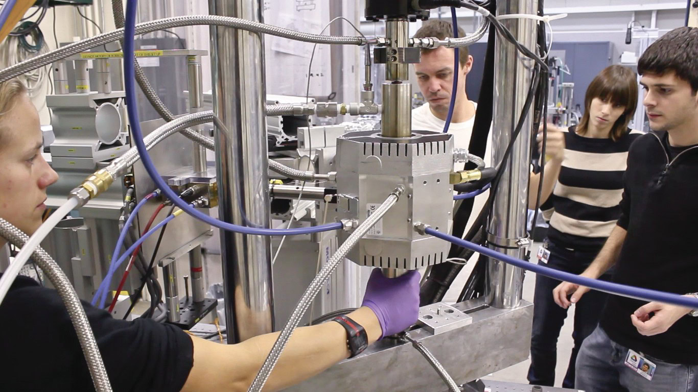
Figure 5. The team works to integrate instrumentation at the 1-ID beamline at the Advanced Photon Source at Argonne National Laboratory. From left: Janine Wischek, Kevin Knipe, Carla Meid, and Albert Manero. Credit: UCF, DLR
Fortunately, ANL’s Advanced Photon Source (APS) beamline 1-ID has the answer (Figure 5). With clear foresight for the immense potential of such an in situ capability, beamline scientists have been steadily developing instrumentation and optics to enable measurements and gain unparalleled material insights. The instrumentation on ANL’s 1-ID beamline includes a mechanical loading frame with a customized base for complete 3D motion and rotation of the sample at high spatial resolution with respect to the beam. The system has been designed can include an in situ furnace along with high-temperature grips and a heat shield for elevated-temperature applications. Previously, beamline high-energy X-rays were used to characterize strain in various ex situ studies of cycled TBC samples, providing important validation of quantitative strains from theoretical models.10 More unique in situ studies on mechanical loading of ceramics11,12 or on phase changes during oxide formation contributed new information, such as significant tensile stresses in the oxide accompanying an associated volume reduction.13
Initial results by UCF and ANL researchers on in situ effects of thermomechanical cycling on TBCs were applied to EB-PVD-coated flat tensile specimens.14 In these tests, an infrared heater provided a thermal cycle that exposed the entire sample to a maximum temperature of 1,121°C. The sample was loaded concurrently with beamline loading frame. The results showed that increasing applied tensile mechanical load induces relief of compressive residual strain in the TGO at the high-temperature point in the cycle. Beyond a critical thermomechanical loading condition, the TGO briefly exhibits in-plane tensile strain at the ramp-up point. These findings were the first quantitative in situ experimental observations of these strains under thermomechanical conditions. These strains are thought to serve as catalysts for crack initiation.
The effect of mechanical loads on observed in-cycle strain range provided insight into the long-term effects in terms of reduced coating life. These findings corresponded with results of numerical simulations from CSU-DLR researchers,15,16 as well as damage evaluation observations from cyclic strain studies. The promising results provided motivation to take on the challenge of incorporating more realistic conditions of thermal gradients for of coated blades approximated as tubular specimens.
There are two primary challenges—achieving high-resolution XRD measurements on hollow cylinder sample geometry and creating a controlled thermal gradient. Slits and sample rotation and/or translation to obtain depth-resolved strains in bulk cylindrical samples overcome the difficulty associated with obtaining XRD measurements on cylindrical samples.17 This effort required contending with the added complexity of a multilayered material system and thermal gradient instrumentation with a furnace surrounding the sample.
The new test facility—based on concepts for cyclic thermal loading of tubular specimens and applying a controlled thermal gradient across the coated specimen wall by internal air cooling and external heating—was developed for the electromechanical test machine at APS. The specimens comprised a 160-mm-long substrate, including a 50-mm-long tubular measurement section with an inner diameter of 4 mm, outer diameter of 8 mm, and a coating system. The directionally solidified substrate of nickel-based superalloy IN 100 DS, consisted of elongated crystallites with crystallographic <100> direction nearly aligned to specimen length axis. This configuration mimicked anisotropic mechanical behavior of superalloy single crystals.
The outer surface NiCoCrAlY bond coat with a thickness of 118 ± 4 μm and a 7–8 wt% YSZ ceramic top coat with a thickness of 211 ± 4 μm were applied by EB-PVD. An infrared radiation chamber heater was customized to provide realistic service temperature conditions of a turbine blade. Radiation of four quartz lamps focused to a center line with elliptical mirrors provided optimal heat flux for a cylindrical specimen. Forced air cooling of the inner substrate wall of the tubular sample set up a thermal gradient. The sample surface temperature was controlled and monitored using thermocouples with an exposed junction in hoop configuration pulled around the specimen.
The thermal gradient was controlled by varying cooling air mass flow while maintaining an external sample temperature of 1,000°C. The precision positioning system at the beamline allows for exact microscale motion of the entire test machine and sample with respect to the focused X-ray beam, while the heater and sample are mounted in a configuration that allows relative movement between them. Circular inlet and exit windows through the center of the front and back heater walls provided access for beam diffraction.
For a tubular sample configuration, axial and radial components of strain can be determined within TBC layers from measurements where the beam grazes the edge of the sample. The X-ray beam passing through the center of the sample additionally provides data for determining the circumferential strain component. Previous studies that vary measurement parameters established that phases in the multilayered TBC system are clearly distinguishable with the grazing approach throughout the depth of the coating. The presence of false doublet peaks from the two-wall transmission that accompanies the through-center measurement approach is an added complexity in determination of quantitative strain from these measurements. In general, however, both techniques are viable and can be used in combination to derive the full strain tensor in each internal layer.7,9 At extreme temperatures, the unique capability to capture dynamic conditions of rapidly evolving strain through 2D diffraction is attributed greatly to small probed volumes from tangential grazing of coating layers with high X-ray energies. This reduces the time required to achieve quality images with microscale spatial resolution, down to five frames of one-second exposure time each.
Data analysis techniques
The response of 2D diffraction rings to changes in lattice structure reflects, with resolution, strain in various phases, and provides a convenient means to distinguish individual constituent behavior within the multimaterial system. Deviation of these diffraction rings over the azimuth with respect to a strain-free radius provides strain for that lattice plane. Strain-free radius values are obtained from a method of measuring a strain-free azimuth angle, determined by measuring distortion of the diffraction ring while increasing applied tensile loading. Here again, high energies associated with synchrotron X-rays and subsequent low diffraction angles imply that measurements are aligned nearly with the axial-radial plane, so that circumferential strains are minimal. The outcome is significant data captured in a single image that, when extended to depth-resolved measurements over time, yields an unmatched wealth of information to track evolution of multilayered material behavior under a dynamic environment.
Capturing a flight cycle
Initial tests performed with varying thermal gradients and mechanical load schemata were intended to determine material behavior from the respective strain response for early cycled TBC specimens. A beam energy of 65 keV was used throughout all experiments. Scanning through coating layers with a window and step size of 30 μm allowed the team to collect XRD measurements across layers, taking advantage of short acquisition times that allowed in situ investigation of time-dependent deformation processes. These one-of-a-kind tests validated some independent effects of parameters and established new findings (Figure 6).
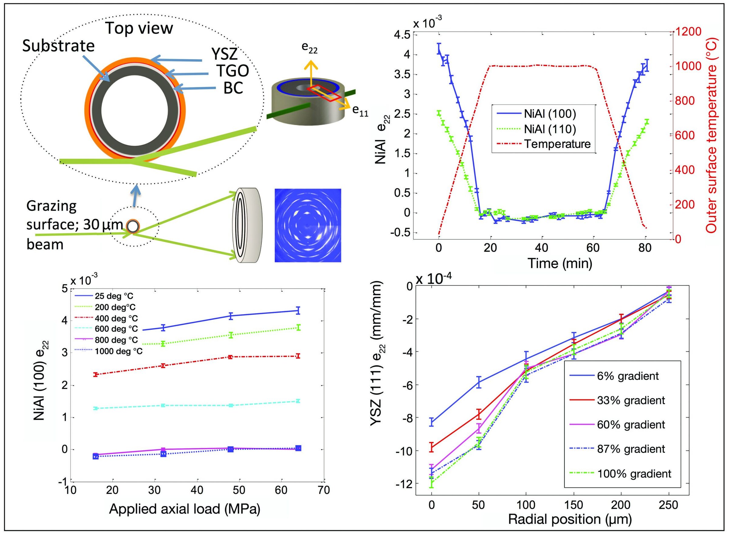
Figure 6. (a) Grazing configuration with (b) resulting strain measurements capturing effects in various layers of a single cycle, (c) mechanical load, and (d) thermal gradients.15 Credit: S. Raghavan
Strain response in single cycle
A typical test cycle exposed a specimen to a ramp-up for about 20 min, a high-temperature hold for about 40 min, and a ramp-down for 20 min. The cycle maintained load and constant mass flow of air through the sample as it collected depth-resolved readings. Measured strain variations in the bond coat validated anisotropy of the NiAl phase and captured the ductile-to-brittle transition with a quantitative measurement of strain rate change occurring at about 600°C.18 This transition for a coating configuration depends on factors such as coating process, phase distribution, composition, heat treatment, and microstructure.1 Understanding this behavior allows appropriate selection of coating parameters, including coating thickness. Top-coat strain profiles across the depth observed during a ramp-up to high temperature reveal that the largest variation of strain and highest strains occur at the interface where these EB-PVD coatings are less porous compared to the surface. The interface is critical for the defect and bond strength information it provides, both of which are affected by cyclic conditions and control the durability of the coatings. Relating the evolution of strains with degradation of the interface strength and initiation of defects facilitates the prediction of coating life and development of a failure model.
Effects of mechanical load
Varying mechanical load at fixed temperatures allowed assessment of individual effects of loading on strain response. Comparing strain slopes at various temperatures revealed reduced load-bearing capacity of the bond coat for temperatures above 800°C, where inelastic behavior is observed. The ability to monitor plasticity and creep relaxation in the bond coat is significant, because it has a direct influence on stress distribution within coating layers and eventual spallation. In addition, low yield strength and creep in the bond coat allow for evolution of TGO pegs and spikes penetrating into the bond coat as the TGO grows, creating defect sites that contribute to eventual failure.
Effects of thermal gradient
Controlling cooling airflow from 0% to 100% of the available airflow allowed variation of thermal gradients, corresponding to a maximum temperature drop across the YSZ layer of about 150°C, which also seen across YSZ coatings of gas-turbine blades in service. We approximated thermal gradient at a prescribed flow using change in spacing between the planes in the atomic lattice (d-spacing) across the layer, as well as measured relationship between applied temperature and d-spacing. We observed significant effects of thermal gradients mainly for the YSZ top coat, with impact most evident at the interface with the bond coat. The trend of increasing strains and strain gradients at the interface is consistent with the notion that the columnar EB-PVD structure presents higher density, lower porosity,19 and, consequently, a higher macroscale elastic modulus closer to the interface. This supports analytical efforts to establish the link between thermal gradients and failure modes in YSZ.20
Future impact
New tests on aged samples with complete depth-resolved profiles for bond coat, top coat, and thermally grown oxide thermal barrier coating systems have started to produce results for comparisons that will relate microstructural characteristics to parameters for life prediction. The results of these tests highlight only the beginning of what we can uncover when advanced measurement techniques and realistic operational conditions are applied to complex material systems.
For TBCs, future measurements have potential to elucidate some of the actual mechanisms behind methods that present improvement in durability, such as addition of reactive elements to the bond coat. Measurements can be used to boost simulation approaches by providing measured material response models representing, for example, TGO growth and creep, as well as providing measured material properties at high temperatures. The contribution toward optimizing design of material systems to meet harsh environments is significant.
This approach can benefit areas of research where processing or operational environment dominates the material behavior with hidden mechanisms to be discerned. Damage tolerance behavior in ceramic-matrix composites and high-temperature coating interactions with additive manufactured materials are some of these future areas of focus.
Conclusion
We have devised novel and innovative strategies to probe material responses under realistic service conditions. Using synchrotron X-rays to analyze these materials during recreated settings has opened doors into new insights about how materials perform—and fail—during real-world use. In situ measurements in recreated environments serve as the link between designing new material systems and performing full-scale engine tests to accelerate the search for revolutionary materials that will change the playing field in propulsion and energy generation.
Acknowledgements
This work is supported by National Science Foundation Grant Nos. OISE 1157619 and CMMI 1125696 and by a German Science Foundation (DFG) Grant No. SFB-TRR103, Project A3. Additional support came from the National Science Foundation Graduate Research Fellowship Program under Grant No. 1144246. Use of the APS, an Office of Science User Facility operated for the United States Department of Energy Office of Science by ANL, was supported by U.S. DOE Contract No. DE-AC02-06CH11357.
Key takeaways
- In situ characterization of thermal barrier coatings (TBCs) on nickel-base superalloy in recreated turbine engine environment
- X-ray synchrotron measurements at high temperature with thermal cycling, thermal gradients, and mechanical loads simulate service environments
- XRD data collected will validate and improve models
- Technique isolates individual behavior of TBC constituents in service for optimizing system design
- Stress and strain gradients increase at interface of top coat and bond coat

Related Articles

Bulletin Features
Emerging Professionals: Science for Society & Future Focus
Science for Society articles: Rishabh Kundu and Ryan C. Eaton: “One small tweak to the lens of materials research, one giant leap for mankind” Grace Dunham: “Microwave firing: Inspiring young scientists through rapid ceramic demos” Hossein Libre: “Shaping materials science through policy engagement” Future Focus articles: Kartik Nemani: “Hope and…

Bulletin Features
Emerging Professionals: Research Articles
Experiential learning: Developing the next generation of engineers By Ryan Eaton When a measure becomes a target, it ceases to be a good measure. Goodhart’s law, coined in reference to monetary policy, is readily applicable to engineering education. When students begin optimizing their study habits to pass an exam rather…

Bulletin Features
Durable and programmable metasurfaces enabled by phase change materials
Controlling light with high spatial precision enables technologies ranging from imaging and sensing to communications. Traditionally, optical components such as lenses and filters rely on bulk materials and fixed geometries, which limit their ability to adapt dynamically. Metasurfaces offer a fundamentally different approach. These materials consist of planar arrays of…