
In recent years, nations around the world have shown increasing interest in deploying advanced nuclear reactors by 2030 to meet rising energy needs and counter the environmental impacts of fossil fuels.1
The radioactive waste from commercial nuclear reactors and legacy weapons programs continues to be a concern, however. Scientists have investigated various waste treatment approaches and waste immobilization forms over the past several decades. Waste forms of interest include hydrocarbon-based materials, polymers, metals, cement or concrete, glasses, ceramics, and glass-ceramics.2,3
Currently, the most commercially viable methods for nuclear waste immobilization are cementation (mixing with cement) and vitrification (converting into glass).2,3 Both of these forms can be easily tailored to contain a range of different waste streams, but they have some drawbacks.
While cement waste forms are low cost and can be fabricated with water at ambient conditions, they have low waste loading percentages due to chemical and thermal limitations and can only handle low-level waste.2 On the other hand, glass waste forms can immobilize both low- and high-level waste streams,3,4 but manufacturing them requires high melting temperatures. Mixing the glass-forming constituents with radionuclides can decrease the melting temperature, but it also lowers the waste loading percentage.4
Understanding the benefits and limitations of these various waste forms allows for innovation and discovery of new material systems for nuclear waste immobilization. For example, cermets, or the family of ceramic–metal composites often used in cutting tools and electronics, could combine the best qualities of both ceramics and metals.
Ceramic waste forms have been the focus of many studies due to their stable crystal structures, which mimic natural minerals with proven stability over extended geological time scales. However, ceramic waste forms are not commonly used due to high processing temperatures comparable to or in excess of those required for glass waste forms, and they require long-term testing to determine their viability.1,2 On the other hand, metal waste forms are uncommon because metallic wastes are prone to reacting with environmental stimuli, such as water and oxygen, resulting in corrosion and leakage of the toxic wastes within a short time frame.
Cermets consist of both ceramic and metallic phases.5–8 This structure gives cermets the high melting point and wear resistance of ceramics along with the toughness and ductility of metals. Thanks to these unique properties, cermets are a promising candidate to contain both low- and high-level waste streams from different advanced reactor types in a single waste form.9
To fabricate cermets, hot pressing techniques are commonly used because they can maximize the material’s densification while decreasing the porosity of the system.10,11 However, hot pressing is typically done in batches, which complicates the goal of continuous processing of nuclear wastes. It also complicates scaling up the process due to limited size and geometry options.
Spark plasma sintering (SPS) is an alternative sintering technique that could offer a potentially better way to densify cermets. SPS applies an electrical current, either pulsed or direct, to induce Joule heating along with some plasma effects between particle surfaces, which leads to consolidation of the particles in minutes. In contrast, other traditional and advanced sintering techniques generally take multiple hours or days to produce dense compacts.12
We recently explored the potential of SPS processing of cermets in our lab at Alfred University. We used 316 stainless steel (SS316) powder and either oxide (zirconia, ZrO2) or nonoxide (silicon carbide, SiC) ceramic powders to fabricate the model cermet system. These powders were sintered using either hot uniaxial pressing (HUP) or SPS to determine the processing limits of densification, which is critical information for scaling up commercial production of advanced cermet waste forms.
Experimental procedure
Zirconia powder and silicon carbide powder were combined with 316 stainless steel powder to produce the model cermet samples (Table 1). A FCT Systeme GmbH SPS and Thermal Technology hot press were used to sinter the samples.
The zirconia powder’s maximum particle size of 5 μm (Figure 1a) makes its agglomeration much easier in ambient conditions compared to the larger particle sizes of the silicon carbide (37 μm) and SS316 (45 μm) powders. Regarding the latter powders, the silicon carbide powder is elongated and angular (Figure 1b) while the SS316 powder is relatively spherical (Figure 1c). These form factors are important in compaction and sintering of the powder, where optimum particle size and distribution promote high densification. Due to the ductility of metals, the SS316 powder can deform and encase the ceramic powders to create a continuous metal phase. The change in metal-to-ceramic ratio also allows for a range of densities and microstructural changes, with the benchmark goal of more than 95% density and less than 5% porosity.
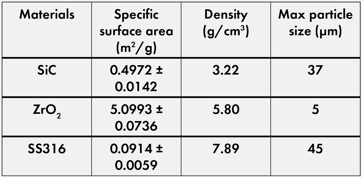
Table 1. Raw powder characterization. Powders and particle size information for silicon carbide and zirconia from Sigma Aldrich and for 316 stainless steel from Goodfellow. Specific surface area and density calculated using an AccuPyc II TEC pycnometer and Gemini VII surface area analyzer, both from Micromeritics.Credit: Nathaniel Marrero
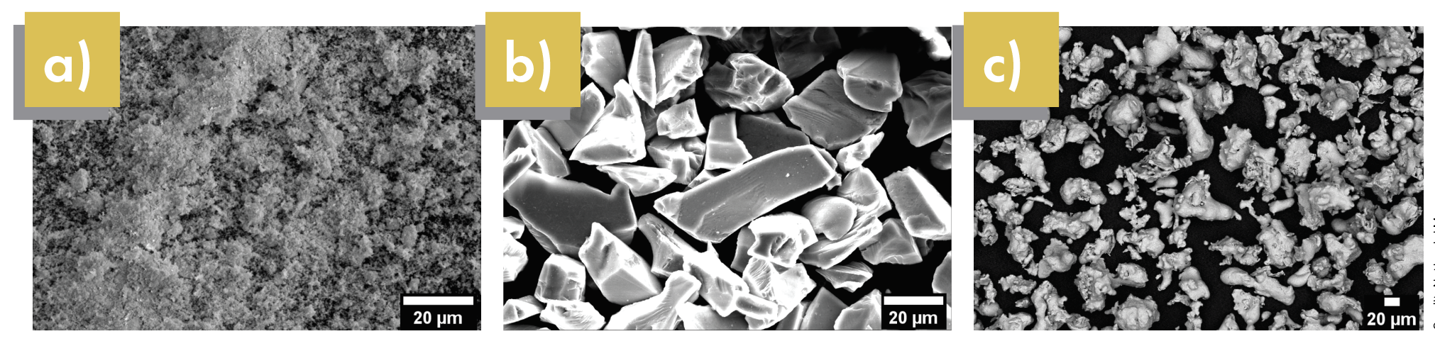
Figure 1. Scanning electron microscopy images of a) zirconia, b) silicon carbide, and c) 316 stainless steel starting powders. Credit: Nathaniel Marrero
Because of differences in the heating schedule between SPS and HUP, two sets of processing schedules were created to sinter oxide and nonoxide cermets. Both processes use lower temperatures than other waste form synthesis methods, specifically glass-based waste forms, which typically require temperatures around 1,150°C.4 The sintering profiles for both SPS and HUP can be seen in Figure 2.
An initial mix of metal and ceramic powders in different volume percent ratios was packed in a graphite die assembly. Graphite foil served as both a high-temperature lubricant for the graphite pressing rod to compress the sample and as an encapsulating material to prevent interaction between the samples and the graphite die. As known from the literature, the metallic phase functions as a binder (or continuous) phase around the ceramic particles by way of liquid phase sintering (LPS).6,13,14 LPS is a common technique used to enhance densification by introducing a phase with a lower melting temperature than the other phases. Once this former phase melts, the resulting liquid provides a faster diffusion path for rapid sintering.11,15
LPS is useful for nuclear waste processing because as sintering temperatures go higher, the chance of volatility of radioactive species increases as well. Volatility temperatures range for different species, but in general, temperatures above 1,000°C can cause volatility unless the radioactive species are suitably incorporated into the waste form. By employing LPS, the sintering temperature of cermets can be lowered to a maximum of 1,100°C in hot pressing and 900°C in SPS.
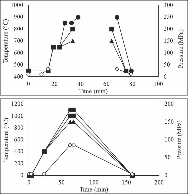
Figure 2. Heating and pressure profiles for SPS (top) and HUP (bottom). Heating profiles are the filled markers, and pressure profiles are the hollow markers. Credit: Nathaniel Marrero
After sintering, samples were ground and polished using silicon carbide disks (60 to 800 grit) and then further polished using diamond suspensions (15 μm to 0.25 μm). Surface oxidation of the samples was observed after polishing, and this oxidation was removed by a 1 M citric acid solution and subsequent deionized water bath. The samples were then placed in a drying oven at 100°C for at least 24 hours to remove any water trapped in the sample. After drying, scanning electron microscopy and energy-dispersive X-ray spectroscopy (SEM-EDS) was used to analyze the microstructure of the cermet samples.
Finally, each sample was cut into four sections using a diamond blade saw for density and apparent porosity measurements by the immersion method (ASTM C373-18).16 The four measurements for each sample were averaged to get the final porosity and density values of each cermet composition.
Results and discussion
Density and porosity analysis
In general, density values of more than 95% with less than 5% porosity could be achieved for all the cermet samples under certain processing conditions (Figure 3). Issues with mixing the initial powders created some variations in the data, particularly at higher ceramic volume percents, which caused some inconsistency in the trends of the data. Regardless, the results still provide a guideline for achieving high densities and low porosities, meaning that an added short mixing step would ideally solve the issue of the mixed trends in the data.
For 20:80 volume percent samples, both oxide and nonoxide cermets achieved the density and porosity benchmarks. However, for the ZrO2:SS316 samples below temperatures of 900°C and 1,000°C in SPS and HUP, respectively, the density and porosity did not meet the desired benchmarks. For SiC:SS316 samples, the density values during HUP processing are about the same at all temperatures, while 700°C in SPS is not high enough for desirable densification.
The 35:65 volume percent oxide cermets presented mixed trends over the temperature range in SPS but showed linear trends in HUP (i.e., density increased with temperature). Ultimately, the only optimum temperature for these samples was 1,100°C in HUP. Meanwhile, the 35:65 volume percent SiC:SS316 samples showed a similar trend to the 20:80 volume percent samples.
For the 50:50 volume percent cermet samples, mixed trends indicated that at this ratio, the temperature range was adequate for sintering the cermets. At the higher temperatures, the cermet samples are sufficiently densified to achieve the benchmark set for these samples.
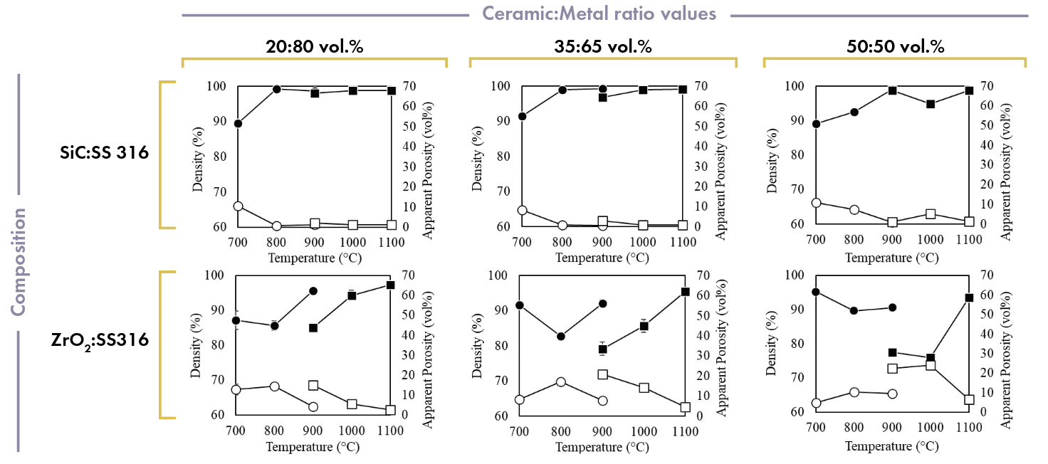
Figure 3. Cermet sample density and apparent porosity. Black markers indicate density values and white markers indicate apparent porosity. Credit: Nathaniel Marrero
Microstructural characterization
Using SEM-EDS images, maps of both the oxide and nonoxide cermet microstructures were analyzed. SiC:SS316 systems showed limited interaction between the ceramic and metallic phases; however, some overlap suggests the formation of secondary carbides. Additionally, the microstructural analysis and elemental distribution in the ZrO2:SS316 system show there was a higher intensity of elemental chromium and molybdenum, the alloying elements in SS316, at or near the ceramic–metal interface. The intensity is greater when combined with zirconia compared to silicon carbide, as shown in Figures 4 and 5.
Carbide cermets
In SiC:SS316 samples, the elemental distribution of the metallic species can be seen as a continuous phase surrounding grains of silicon carbide. Overlayed EDS elemental maps show coexistence of metallic species, such as iron with nickel and chromium with molybdenum, in the microstructure (Figure 4).
Further inspection reveals that all four main components of SS316 are contained in the metal binder phase with minimal growth of a native oxide film on the SS316 particles. At the highest processing temperature, the SEM-EDS images show evidence of dissolution of the metallic species into the silicon carbide grains. This dissolution supports our observation of possible secondary carbide formation in the cermet samples.
Although silicon carbide grains can be seen as black regions in the metallic phases of the SEM images, the metallic species can form eutectics, leading to potential carbide formation. These eutectics lower the melting temperature of the SS316, which is beneficial for reducing processing requirements for producing dense cermet samples.
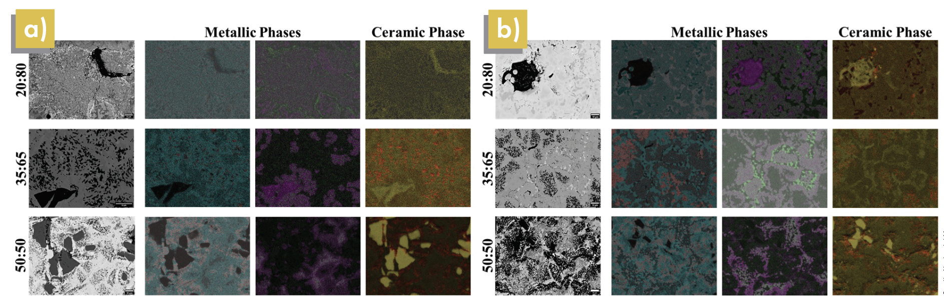
Figure 4. SEM images (left-most greyscale columns) and EDS maps (colored columns) of a) SiC/SS316 samples at 900°C in SPS and b) SiC/SS316 samples at 1,100°C in HUP. In metallic phases: Blue = iron, Red = nickel, Green = molybdenum, Purple = chromium. In ceramic phases: Red = carbon, Yellow = silicon. Credit: Nathaniel Marrero
Oxide cermets
In the SPS EDS maps (Figure 5), elemental chromium and molybdenum can be seen with great intensity both in the metallic binder phase and at the edge of the ceramic–metal interfaces. However, in HUP EDS images, the intensity of chromium and molybdenum at ratios of 35:65 and 50:50 do not have as distinct of lines as their counterparts in SPS or at a ratio of 20:80. As mentioned before, the electric current applied in SPS imparts enough energy into the cermet system to allow for preferential arrangement of metallic species in the binder phase. At 1,100°C in HUP, there is not enough thermal energy for this rearrangement to happen at higher volumetric ratios of ceramic-to-metal powders. This constraint is due to the difference in how heat is applied to both systems, with induction being the heat source in HUP and the resistivities of materials determining the current and heat applied in SPS.
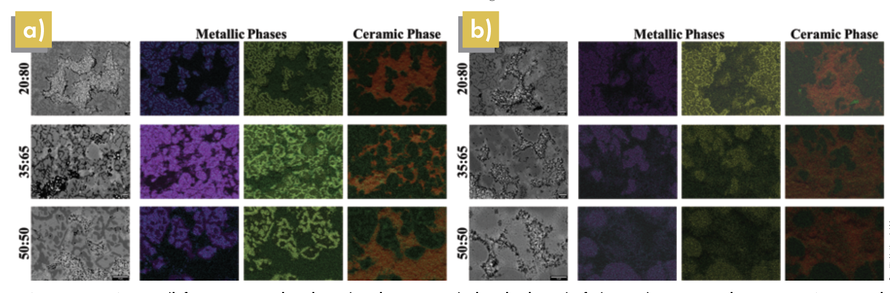
Figure 5. SEM images (left-most greyscale columns) and EDS maps (colored columns) of a) ZrO2/SS316 samples at 900°C in SPS and b) ZrO2/SS316 samples at 1,100°C in HUP. In metallic phases: Blue = iron, Purple = nickel, Green = molybdenum, Yellow = chromium. In ceramic phase: Red = zirconium, Green = oxygen. Credit: Nathaniel Marrero
Native oxide film growth
It is well known that the addition of chromium and molybdenum in SS316 promotes corrosion resistance by reacting to form a beneficial passivation oxide layer on the steel. But while chromium and molybdenum typically form an oxide layer quite readily, that formation can be impeded by the iron present in stainless steel.17,18 By packing the samples in an open-air environment, the native oxide on these steels remains.
EDS mapping of the 35:65 and 50:50 ZrO2:SS316 samples showed limited growth of the passivation oxide layer (Figure 5). The reduced oxide layer formation results from a higher oxide content, relatively short dwell time, and induction heating.
Although it is difficult to measure precise partial pressures in a cermet sample, Ellingham diagrams can offer insights into the formation of oxides in our samples. Figure 6 shows an Ellingham diagram of common oxides and carbides that could form in our cermet samples.19
As the constituent elements interact in the cermets during sintering and processing, the slope of the lines in the diagram will change significantly, leading to their intersection within the temperature range. Thermodynamically, chromium oxide is energetically favorable to be formed during sintering. Iron oxide and molybdenum oxide can also be formed at lower energies than carbide formation.
Further testing on the cermet samples is required to determine how the oxide layer affects the chemical durability of the cermets and their ability to immobilize advanced nuclear wastes.
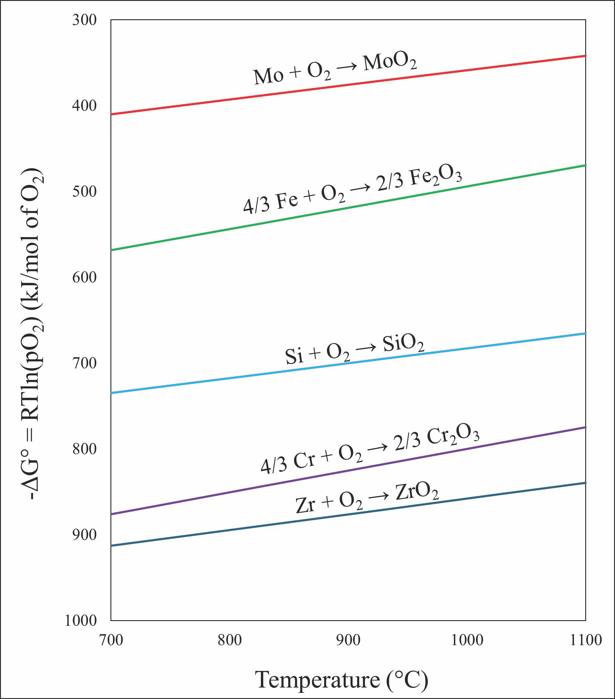
Figure 6. Ellingham diagram of oxide formation in current cermet samples. Diagram plotted using the ΔG of formation values found in Reference 19. Credit: Nathaniel Marrero
Factors affecting native oxide film growth
Oxygen vacancies in the oxide cermet may aid in the formation of an oxide layer. This possibility can be inferred from the work of De Souza and Appel,20 who used density functional theory simulations to study oxygen vacancies in zirconia as candidates for carbon dioxide capture. They found vacancy formation was an energetically taxing process in zirconia without any dopants. When zirconia was doped with a 2+ cation such as calcium, however, the dopant eliminated an oxygen atom to account for the charge imbalance. This elimination allowed for an oxygen vacancy at a lower energy cost to the system, thus opening the door to a more thermodynamically stable zirconia surface.
Although this research was for a different application, these interpretations could be extended to the oxide cermet samples. If a 2+ cation allows for the creation of oxygen vacancies, this phenomenon likely could be applied to the metallic components of the SS316 to create a passivation layer. Barring differences in atomic differences between calcium and the metallic species of SS316, the surface oxygen vacancies and ejected oxygen could be a source of oxygen for the oxide layer in addition to the native oxide film.
This interpretation of oxygen vacancy formation supports our argument as to why the intensities of chromium and molybdenum were much less in the SPS case than the HUP case. A detailed density function theory analysis of this cermet system—or of a chromium-doped zirconia sample—would further validate this theory. For the purpose of this paper, however, it is presented as potential supporting evidence.
Another factor to consider in the oxide layer formation is the radius dependence on atomic movement. Fu et al. previously investigated this phenomenon in oxide ceramics,21 and one can apply the same argument to cermets. A radii mismatch can be calculated using the equation 100 × (ra–rb)/ra, where ra = solute radii and rb = solvent radii.
As seen in Table 2,22 chromium and molybdenum have two of the lowest radii mismatches with zirconium, suggesting these ions have a higher probability of migrating in the metallic phase toward zirconium sites to enhance the native oxide layer. This layer can aid in the corrosion resistance of these waste forms, which is beneficial for storage in deep geological repositories.
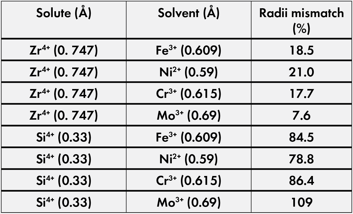
Table 2. Radii mismatch data using calculated radius data from Gosh et al.22 Credit: Nathaniel Marrero
The migration of chromium in these samples can be another indication of cermets’ ability to offer high oxidative corrosion resistance for nuclear waste forms. That is because given adequate oxygen vacancy formation, chromium can create an energetically favorable surface between the 316 stainless steel and zirconia grains to create a passivation layer, assuming the same phenomenon proposed by De Souza and Appel applies.20
Our SEM-EDS data show that for a given area, elemental chromium and molybdenum are present in similar amounts, but chromium shows the most prominent migration. As chromium migration is observed above 800°C, the higher end of the processing window is more favorable in SPS no matter the ceramic-to-metal ratio. However, with HUP, the 20:80 vol.% mixture showed chromium migration similar to that of the SPS samples, while the other two mixtures had less evident chromium migration. This behavior may be attributed to the electrical current in the SPS, allowing for an enhanced migration of metallic ions.
The EDS maps in Figure 5 shows oxide film growth as a function of metallic content, supporting our suggestion that the same phenomenon proposed by De Souza and Appel applies.20 This growth allows more chromium to migrate toward existing oxygen vacancies with higher alloy compositions.
In addition to oxide film growth, our interpretation of the migration phenomenon also explains the absence of chromium migration in the carbide cermet sample within the limits of the SEM-EDS. Strong covalent bonding between silicon and carbon requires higher energy and affinity for chromium to migrate from stainless steel into the chrome-free silicon carbide.
Besides the migration phenomenon, the Acheson process, a common formation method for silicon carbide that uses silica and carbon, and various kinetic models have been developed to understand the mechanics driving oxidation of silicon carbide.23,24 Though a silica layer can be present on the surface of silicon carbide powder, this layer is typically minimal and would not enhance the oxide layer on SS316.
Finally, secondary silicide and carbide formation are more probable due to the resistance heating in SPS, forcing the breakdown of silicon carbide at lower temperatures. The inert atmospheres used in both sintering processes prevent additional oxygen incorporation and limit oxide interactions with SS316. Consequently, fewer oxide species in carbide cermets restrict the formation of oxide growth in nonoxide cermets.
Conclusions
Cermets offer a unique solution for containing both low- and high-level waste streams in a single waste form, thus allowing safe storage of these materials and decreasing the need for multiple repositories. Based on our study, cermet systems can be successfully sintered using SPS under a less energetically taxing and faster process compared to hot pressing.
Furthermore, microstructural analysis of the cermet samples identified a metallic binder phase with the growth of an oxide layer at the ceramic–metal interfaces in oxide cermets, which may enhance the corrosion resistance in cermet waste forms. These secondary phases were formed through LPS of the binder phase.
Ultimately, our findings support further investigation of cermets as a viable candidate for nuclear waste forms. Further research into the chemical durability of these cermets and radiation stability is required to classify cermets as an effective nuclear waste form.


Related Articles

Market Insights
The evolving discipline of demand forecasting can improve competitiveness and control costs
What does the future hold? It is a question that everyone has contemplated at one time or another, and a mystery that has obsessed writers, mystics, philosophers, clerics, astrologers, and others for centuries. For businesses, the question is more than philosophical. Discovering clues to what is next is essential to…

Bulletin Features
Sustainable ceramics production: Environmental considerations in tile manufacturing
Ceramics are often regarded as a sustainable material choice thanks to their high durability and chemical stability, which enable a long service life. But ceramics come with environmental baggage in other areas, such as raw material sourcing, processing, and disposal. The specifics of this baggage are unique to each ceramic…

Market Insights
Financing the responsible supply of energy transition minerals for sustainable development
As the world transitions to sustainable development and the achievement of net-zero emissions by 2050, the demand for specific minerals and metals, such as lithium, nickel, and copper, is surging. These minerals are crucial for the development of batteries, solar panels, and electric vehicles, and therefore are central to clean…