
Amongst the various composite materials, nacre-like composites propose to leverage the brick-and-mortar microstructure found in the nacreous layers of seashells to achieve an unusually high combination of strength and toughness.1
Nacre consists of 95 vol.% aragonite, a crystallographic form of CaCO3, and 5 vol.% of organic matter, mostly protein and chitin. Although pure aragonite microplatelets are hard and brittle, the addition of a thin organic layer between them endows nacre with a fracture toughness three to nine times higher than that of the hard CaCO3 tiles, in dry and hydrated states, respectively.2
Numerous nacre-inspired composites have been developed, with the common feature that they all reproduce some kind of alignment of 2D microreinforcements, such as ceramic microplatelets or other 2D nanosheets.3 However, these composites may not display all the microstructural key features of nacre when they contain low concentrations of reinforcing elements dispersed in a softer matrix.
Nacre-like ceramic composites with a metallic mortar could combine the excellent toughness of metals with the high-temperature resistance of ceramics (Figure 1). To assess whether these expectations for nacre-like ceramic–metal composites can be achieved, this paper reviews the existing developments in the processing of such composites.
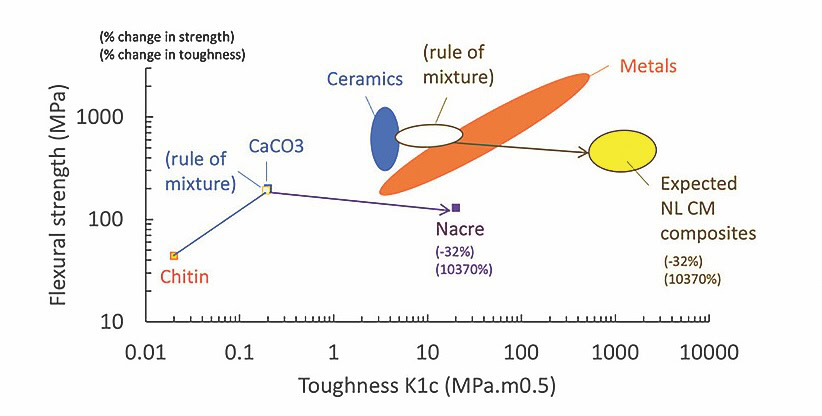
Figure 1. Toughness–strength performance map representing natural nacre (purple) and the hypothetical nacre-like ceramic–metal (NL CM) composites (yellow). Natural nacre and nacre-like ceramic–metal composites outperform their individual components as well as the predictions from the rule of mixture (10,370% increase in toughness as compared to the rule). They do, however, demonstrate a slight decrease of -32% in flexural strength. Credit: Kumar and Le Ferrand, JACerS
General overview of fabrication approaches
With the increasing research in nacre-like ceramic–metal composites, a variety of fabrication processes have been explored, revealing two main routes (Figure 2A):
- Route I consists of fabricating a continuous ceramic scaffold first, then infiltrating that ceramic scaffold with molten metal, either with or without the use of pressure. A hot-pressing step can serve as a final densifying and consolidating step.
- Route II consists of co-assembling ceramic and metal powders followed by their compaction, typically using a high-temperature pressing step.
Route I processes are very similar to the processes used for making nacre-like ceramic–polymer composites, where a thermosetting resin is infiltrated into a ceramic scaffold and crosslinked. Route II processes resemble ceramic processes, where slurries containing various types of particles are processed and consolidated together.
These processing routes have been explored for developing various specific compositions. Figure 2B illustrates the development of various types of nacre-like ceramic–matrix composites over the years, revealing the accelerated development in the past decade.

Figure 2. Processing routes for making nacre-like ceramic–metal (NL CM) composites. (A) Schematic illustrating the various processing steps. (B) Overview of the processing steps developed over the years for various compositions. Different colors indicate different metal mortar phases: aluminum and aluminum alloy in blue, nickel in maroon, copper in orange, magnesium and magnesium alloys in purple, iron in grey, titanium–niobium–titanium in pink, copper–nickel in gold, aluminum–copper in light blue, bulk metallic glass (BMG) in green. The compositions of the ceramic phases are written on the graph next to their symbol. Credit: Kumar and Le Ferrand, JACerS
Route I fabrication: Ceramic scaffold and metal infiltration
Route I first builds a porous ceramic scaffold with aligned features, which is then infiltrated with molten metal and eventually pressed as a final densification step. There are three main processes reported for route I: freeze casting, 3D printing, and vacuum filtration.
Freeze casting
In a typical freeze-casting process, a suspension of ceramic particles in water is frozen under a controlled directional temperature gradient, leading to the growth of lamellar ice crystals. These unidirectional crystals create a unidirectional structure that imitates the aligned structure in nacre. Subsequently, the ice is removed via sublimation, leaving behind the porous ceramic scaffold. This scaffold is consolidated by sintering before being infiltrated by a molten metal, leading to the nacre-like ceramic–metal composite.
This method allows the development of materials with intricate microstructures, achieved by carefully regulating the freezing process and the kinetics of ice crystal solidification. Traditional unidirectional freeze casting, where cold is applied at the bottom surface of the vessel into which the suspension is deposited, can be tailored to create more complex freezing patterns. For example, bidirectional freeze casting can control the ice crystal structure in both longitudinal and transverse directions.4
3D printing
This process involves the 3D printing of ceramic scaffolds followed by infiltration with molten metal. Typically, computer-aided design is used to design the 3D porous geometry, which is then realized using stereolithographic 3D printing using polymeric inks containing ceramic particles. The 3D-printed green parts are sintered with supportive structures to prevent warping and distortion at high temperatures to yield the ceramic scaffold.
Before infiltrating the molten metal, the volume of the voids are calculated based on the density of the scaffold, and 15% more volume of metal than the estimated volume of voids is used to ensure complete infiltration. Khan et al.5 used this strategy to print silica scaffold infiltrated with aluminum using centrifugal force. Although only stereolithography has been reported to be used for making nacre-like ceramic–metal composites, other 3D printing methods for making porous ceramics with aligned microstructures can be used, such as extrusion-based direct-ink writing or magnetic drop-on-demand 3D printing.
Vacuum filtration
Another approach for fabricating ceramic scaffolds involves the alignment of ceramic platelets by vacuum filtration, followed by partial sintering for consolidation. The scaffolds are then infiltrated with molten metal to form a nacre-like ceramic–metal composite.
This method was presented by Liu et al.,6 where titanium aluminum carbide platelets of sizes ranging from 100 to 300 nm were dispersed in ethanol at a mass ratio of 3:40 through ultrasonication and ball milling. The suspension was poured into a funnel and filtered through a nylon membrane with a pore size of 0.1 µm under a vacuum pressure of about 0.06 MPa, promoting the horizontal alignment of the platelets as they deposited onto the membrane. The resulting bulk material was dried, subjected to vertical pressing at 72 MPa for one hour, and partially sintered in a flowing argon atmosphere at 900°C for one hour. The titanium aluminum carbide scaffold with open pores was subsequently infiltrated with molten AZ91D alloy in a flowing argon gas at 850°C, a temperature higher than the melting point of the alloy, and then naturally cooled in the furnace to obtain the nacre-like ceramic–metal composite.
Route I methods create aligned ceramic scaffolds. Other methods for creating such scaffolds than those described here exist, although they have not yet been employed for producing nacre-like ceramic–metal composites. For example, the electrical or magnetic orientation of particles can be used to assist the horizontal alignment of the particles.7 The infiltration of the molten metal can also be done with or without the application of pressure.
Route II fabrication: Powders co-assembly and hot pressing
Route II processes co-assemble the ceramic and metallic components together at the same time and consolidate everything using hot pressing. There are five main processes reported for route II: lamination, slip casting, magnetically assisted slip casting (MASC), spark plasma sintering (SPS)-assisted assembly, and coextrusion.
Lamination
In this process, tapes made up of ceramics through tape casting are laminated with metal sheets to create a horizontally aligned structure. The laminated layers are then consolidated via hot pressing. During the hot pressing, the metallic foils melt and partially infiltrate the tape-casted ceramic scaffolds while making a continuous metallic phase. Metallic foils of various compositions can be used in this method as well as combined compositions.
This process was the first one utilized for the biomimetic design and processing of laminated boron carbide–aluminum composites.8 This process has also been used to form nacre-like ceramic–metal composites made of zirconium boride–silicon carbide and titanium–niobium–titanium.9
Slip casting
Slip casting is another process derived from the ceramic industry, where a slurry containing particles is cast onto a porous mold that drains the liquid from the slurry before drying and sintering.
The method has been applied to slurries containing nickel-coated alumina microplatelets that aligned due to gravity during the slip casting.10 The green bodies were rapidly sintered using SPS at 1,100°C or 1,200°C. Dewetting of the nickel mortar during sintering was prevented by using a mixture of nickel oxide-coated and nickel-coated alumina platelets. To obtain a high packing density in the green bodies, a high solid loading (50 wt.%) was employed in the slurry used for slip casting.
Magnetically assisted slip casting
MASC combines slip casting with the magnetic orientation of ceramic and metallic anisotropic particles. Nacre-like alumina–copper composites have been obtained by this process, followed by densification through hot-pressing at 1,150°C for 60 min at about 60 MPa pressure.11
This method has also been applied to slurries containing iron-coated alumina microplatelets, followed by pressure-assisted densification at 1,450°C to make nacre-like alumina–iron composites.12 The iron coating of the alumina microplatelets was conducted using a nonaqueous sol–gel reaction using a metal–organic precursor dissolved in benzyl alcohol, followed by a reduction reaction in a 5 vol.% hydrogen–nitrogen atmosphere at high temperature. The volume fraction of the metal in the composite was controlled by tuning the relative amount of precursor used in the sol–gel reaction to ensure the coating, which effectively formed the metallic matrix after MASC and hot pressing.
A similar method used nickel-coated alumina microplatelets produced using electroless plating to create nacre-like alumina–nickel composites.13
Spark plasma sintering-assisted assembly
In this assembly method, ceramic platelets and metal flakes are mixed together and consolidated directly using SPS. The unidirectional pressure provides the force for the nacre-like horizontal alignment.
Fontoura et al. utilized this technique to consolidate multilayer graphene flakes with copper precipitates into a nacre-like ceramic–metal composite.14 The flakes were dispersed in a solution of copper sulfate salt with acetic acid in deionized water. The acetic acid in the solution activated the surface of the flakes, imparting a partial negative charge that attracted the positively charged copper ions. A cementation reaction between magnesium and copper ions was then carried out, where more reactive magnesium oxidized, reducing the copper ions on the flakes’ surface. The resulting multilayer graphene–copper powder was consolidated using a graphite die in SPS.
In a different approach, Cao et al. used flaky copper powders to promote the in-situ growth of graphene under a controlled atmosphere, yielding a graphene/flaky copper composite powder.15 This powder was then mixed with graphite flakes and densely stacked into a graphite die, which was compressed at 900°C in a vacuum under a pressure of 50 MPa for one hour to produce a nacre-like graphene–copper composite.
Similarly, Yang et al. used a graphene oxide colloid with Cu(CH3COO)2 • H2O to prepare reduced graphene oxide/copper composite powder after reducing the mixture of powders in hydrogen–argon gas.16 The as-prepared composite powders were pressed and sintered using SPS at 600°C for five minutes under vacuum at a pressure of 40 MPa to form the layered reduced graphene oxide–copper composite. Similarly prepared reduced graphene oxide–copper nanocomposite powders were compacted by Hwang et al. in a graphite mold at 600°C for three minutes under vacuum in SPS at an applied pressure of 50 MPa.17
In another study, a layered composite was obtained by stacking layers of copper- and nickel-electroplated titanium boride–boron carbide plates under a hot pressing sintering apparatus.18 The electroplating process was performed to obtain a layer of copper and nickel over the thin plates of titanium boride and boron carbide. The simplicity of the equipment for this process makes it popular.
Coextrusion
The coextrusion process provides a unique opportunity to fabricate brick and mortar structure by using a feed rod composed of a core and a shell around it. A filament is extruded from the feed rod, which consists of ceramics coming out from the core and a metallic layer around it extruding from the shell. Precise control of metallic coating over the ceramics is obtained through this process, resulting in high-ceramic and low-mortar volume fractions in the final microstructure.
The filaments are then segmented into individual units, representing bricks in the “brick-and-mortar” structure. These segmented filament units are further laminated to form billets with varied orientations and configurations, followed by hot pressing to achieve a densely packed nacre-like ceramic–metal composite.
Capabilities and challenges of current processing methods and alternative approaches
While the microstructures obtained are referred to as “nacre-like,” in reality, there are three distinct types of microstructures obtained for the nacre-like ceramic–metal composites:
- Lamellar microstructures, which correspond to alternating horizontal continuous layers. These lamellar microstructures are for most of the cases obtained by freeze casting or lamination.
- Brick-and-mortar microstructures, which are the typical nacre-like structures desired to achieve high strength and toughness. These microstructures are obtained for most of the powder-based (route II) processes when the concentration of the ceramic phase is predominant.
- Aligned microstructures, which are also obtained from the route II processes and have been mostly obtained through SPS-assisted assemblies. These microstructures do not have a high enough concentration of ceramic phase to form bricks, and the microstructures appear as ceramic particles dispersed in a matrix.
Some processes can produce more than one kind of microstructure or a combination of two microstructures. Freeze casting has produced both lamellar and brick-and-mortar structured nacre-like ceramic–metal composites with pressureless infiltration of molten metal into ice-templated ceramic scaffolds.19 Along with that, bidirectional freeze casting followed by pressured metal infiltration had produced lamellar composites, which upon further hot pressing led to brick-and-mortar composites.4
The processes present various capabilities in terms of mortar and bricks’ thicknesses, aspect ratio, mineral content, and quality of alignment defined by the fast Fourier transform ratio. It is noticeable that the thickness of the metal mortar varies linearly with the thickness of the ceramic brick, and this variation is independent of the process used or of the chemistry of the components. Nacre has a mortar thickness below 20 nm20 for ceramic bricks of 200 nm to 1 µm.21 It appears that only a couple of nacre-like ceramic–metal composites have achieved these dimensions: the nacre-like titanium aluminum carbide–magnesium with brick-and-mortar structure produced through vacuum filtration,6 and the nacre-like alumina–nickel composites with both lamellar and brick-and-mortar microstructure produced by freeze casting22 and SPS-assisted assembly.13 All the other composites have higher thicknesses of bricks and mortar.
The mineral content in nacre-like ceramic–metal composites varies over a long range; however, in actual nacre, the mineral content is quite high, and only a few nacre-like ceramic–metal composites have reached those high values of mineral content. Coextrusion and MASC processes have consistently produced nacre-like ceramic–metal composites with high mineral content in brick-and-mortar microstructure, and a few composites through freeze casting in both lamellar and brick-and-mortar microstructure have also obtained mineral content in similar range. Furthermore, the aspect ratio of the bricks also does not show any obvious trend with composition and process, although the lamellar structure inevitably achieves a very large aspect ratio as per its definition.
The highest aspect ratio realized for the brick-and-mortar structure is about 6–7 and is obtained for processes involving hot pressing or SPS. These highest aspect ratios are obtained for nacre-like ceramic–metal composites with high vol.% in ceramics, around 80 vol.%. The correlation between a high aspect ratio and high mineral vol.% is likely due to the use of hot-pressing that densifies the system quickly while preventing diffusion and grain growth.23 Other methods such as coextrusion or freeze casting also achieve high density but without reaching a high aspect ratio. High relative density and high aspect ratio are two parameters desired in the composites in order to achieve high strength and high toughness.
Finally, alignment is also a parameter necessary to have nacre-like structures with high anisotropy and mechanical properties. The word “alignment” used here refers to the morphological arrangement of the ceramic and metal building blocks. In a nacre-like ceramic–metal composite, the ceramics exhibit a narrow distribution of crystalline orientations in one direction. This alignment is due to the shape anisotropy of the ceramic grains after sintering because of processing conditions, which on a micrometer scale looks like the microstructure of a nacre.
This alignment can be characterized using several methods that make use of crystalline anisotropy in the ceramic, or the shape anisotropy of its grains, such as electron backscattering diffraction in scanning electron microscopes or selected area electron diffraction in transmission electron microscopes. For large area characterization, X-ray diffraction can be used in the ϴ to 2ϴ scan method, four-axis diffractometer, Eulerian cradle, or rocking curves. Other characterization techniques are small angle X-ray scattering, neutron diffraction, and directional reflectance microscopy.
All structures have some degree of alignment because the fast Fourier transform ratio is higher than 1 for all. There is no obvious trend in alignment quality between the lamellar and the brick-and-mortar/aligned structures. However, the alumina–iron composite obtained using MASC followed by unidirectional hot pressing achieved the highest alignment. Three composites have the next highest alignment degree and were obtained by lamination, MASC, and SPS-assisted assembly, respectively, likely due to the use of unidirectional pressure as the final processing step.
In addition to these microstructural considerations, the presence of appropriate connections between the mineral phase is important to increase the strength and provide further energy dissipation mechanisms. Two major types of bridges can be recognized: (1) interpenetrated metal and ceramic phases due to the remaining porosity in the scaffolds before infiltration for route I processes and (2) mineral bridges or mineral connections due to the sintering for route II processes. These connections are either singular points or areas and are rather randomly distributed.
Finally, some nacre-like ceramic–metal composites present an interface layer that helps with the bonding between the metal and ceramic phases. Indeed, dewetting is a common problem between metal and ceramic due to higher contact angles, preventing the adhesion between the two phases. The work of adhesion of metal over ceramic is higher than the surface energy of metal. In that case, it is favorable for the metal to form droplets on the ceramic surface, minimizing the contact area between the two materials. High contact angles may also prevent pressureless infiltration, but in some cases, infiltration is accompanied by reactions that may result in an apparent decrease in the contact angle, facilitating pressureless infiltration. These reactions often result in brittle interfacial products that significantly degrade the properties of the composite.
Two main avenues have been developed to address these issues, both leading to the formation of an intermediate layer between the ceramic and the metal: (1) using coating or (2) by having a reaction between the metal and the ceramic. Examples of coating include coating alumina platelets with nickel oxide to improve interfacial bonding with nickel,10 direct deposition of iron oxide and iron on alumina platelets using sol–gel chemistry,12 and adding a thin layer of copper between titanium boride–boron carbide and nickel.18
The metal oxide coating on alumina platelets undergoes partial reduction, leading to the presence of controlled oxygen concentration, which reduces or eliminates the chance of dewetting during sintering without any interfacial reaction. In other works, in-situ formation of titanium boride with (titanium, niobium) carbon whiskers were used to alleviate interfacial residual stresses, improving the interfacial bonding strength.9
For creating a strong bonding between graphene and copper, copper (II) hydroxide and copper oxide were let to form during the process to allow good interfacial strength due to copper–oxide bond formation before reduction to copper during SPS.16 In another approach, an in-situ cementation process was used to develop multilayer graphene–copper powders, where the surface of the multilayer graphene flakes is activated by acetic acid to deposit copper sulfate and copper ions on the flakes followed by reduction to copper with the use of magnesium.14 Similarly, boron carbide was let to react with titanium hydride to decrease the contact angle and increase the wetting and interfacial bonding of the ceramic to a magnesium alloy.24
The various processes developed thus far to produce nacre-like ceramic–metal composites present a range of capabilities. The freeze-casting approach appears to be the method providing the highest flexibility in terms of microstructural control and volume fraction in ceramics. It is also the most employed method, which is why it has been tested for various composites.
Some other processes such as coextrusion and MASC exhibit more unique specificities, such as achieving a higher concentration of ceramics, smaller ceramic bricks, lesser mortar thickness, and higher quality of alignment. Vacuum filtration has been shown to produce the smallest ceramic bricks and the lowest mortar thickness but with lower mineral content compared with other processes.
Similarly, SPS-assisted assemblies have produced lower mineral content in nacre-like graphene–copper composites with thicker ceramic bricks. However, the same process has also produced nacre-like alumina–nickel composites with higher mineral content and thinner ceramic bricks.
Coextrusion, MASC, vacuum filtration, and SPS-assisted assembly have mostly produced nacre-like ceramic–metal composites with brick-and-mortar structure. On the other hand, freeze casting is flexible enough to produce both lamellar and brick-and-mortar structures, while tape casting has predominantly produced lamellar-structured nacre-like ceramic–metal composites with larger ceramic brick sizes and higher mortar thickness.
There is still a large research space to explore more extensively across various combinations of metals and ceramics as well as to achieve brick-and-mortar structures with high aspect ratios and high mineral content. The high temperatures used during the sintering process pose a challenge to this aim due to the ceramic grain coarsening during densification.
The research on nacre-like ceramic–metal composites could build on the results of sintering methods of high-performance ceramics, for example, by exploring microwave sintering or ultrafast high-temperature sintering. Other features such as the surface roughness of the ceramic bricks that are found in nacreous seashells and reproduced in nacre-like ceramic–polymer composites could also be further explored with metallic mortars.
In the future, continued research on nacre-like ceramic–metal composites is essential to realize their potential in the development of advanced engineering materials, suitable for a wide range of applications.
*This article is excerpted from “Nacre-like ceramic–metal composites: State-of-the-art, challenges, and opportunities,” JACerS 2025, 108(11): e20623.


Related Articles

Bulletin Features
The nonferrous metals market: Supply and regulatory pressures inspire strategies for a resilient future
Nonferrous metals serve foundational roles in the electrification, renewable energy, and digital transformation. Nonferrous metals are metals that do not contain iron in significant amounts. These metals typically are nonmagnetic, corrosion resistant, electrically and thermally conductive, and lightweight, making them ideal for applications in the emerging markets mentioned above. Even…

Market Insights
Industrial digitalization: ‘Smart’ operations can improve worker safety and well-being in high-temperature environments
Heavy industry is the backbone of economies around the world, critical to automotive production, construction, the energy sector, and everything in between. But many heavy industries are facing worker shortages. There are more than 400,000 open manufacturing jobs in the United States, according to the Bureau of Labor Statistics.1 With…

Market Insights
‘Fail fast’ manufacturing: How disciplined experimentation strengthens, not threatens, quality
In manufacturing, few phrases raise eyebrows faster than “fail fast.” In the startup world, this business strategy is celebrated as a sign of agility. On a ceramic manufacturing floor, it can sound careless or even dangerous. In manufacturing, few phrases raise eyebrows faster than “fail fast.” In the startup world,…