
Society today consumes a huge amount of energy. As second- and third-world countries progress and first-world countries integrate more technology into their lifestyles, conservation efforts are not enough to slow energy consumption. Fossil fuels, such as natural gas and oil, are increasing in importance. Nuclear energy continues to be important, even though some countries, such as Germany, have announced plans to replace it with renewable energy sources. Renewable energy sources continue to improve and will be important in the future energy portfolio. Microspheres and microcapsules long have been used in the pharmaceutical, food, cosmetic, chemical, and livestock feed industries. Advances in energy generation technology call for new approaches to maximize efficiency and safety—microspheres and microcapsules may offer effective solutions.
Microspheres and microcapsules for energy applications include several forms, such as encapsulated chemicals in self-healing coatings over ceramics, high-temperature insulation, and proppants for shale oil and gas recovery. In some cases, they can be the energy source itself, for example, as nuclear fuel or solar cells.
Granules produced with conventional processes, such as spray drying or cooling, spheronization, extrusion, or dripping, have drawbacks, such as, broad size distribution, shape irregularity, low density, “onion shell” structure, difficult scale-up, and cost control. All these problems can be overcome with a versatile, scalable, and cost-efficient process for producing unimodal particles of highly spherical shape out of almost any imaginable material.
Fusion process for producing microspheres and microcapsules
Today, there are increasing applications for microspheres and microcapsules produced using the laminar flow drip-casting, or vibrational nozzle, process. Brace GmbH (Karlstein, Germany) has been applying Rayleigh’s theorem of droplet formation of laminar liquid flows to industrial-scale manufacturing for more than 25 years.
This process produces microgranules in many sizes and materials as well as matrix-encapsulated microspheres and core–shell-encapsulated microcapsules (Figure 1).
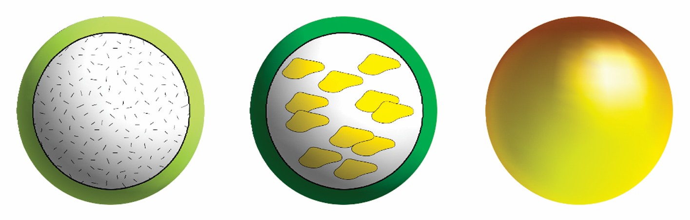
Figure 1. Microspheres and microcapsules contain a variety of core contents to suit specific applications. From left: Microcapsule with a solution core, microcapsule with a cell suspension core, and microsphere with a matrix-encapsulated active agent. (Credit: Brace GmbH.)
The main difference between microspheres and microcapsules is the release profile. Microspheres usually have diffusion-controlled release profiles with a permanent release rate that is kinetically controlled by the particle size. In contrast, microcapsules expel their content in a single burst as the shell breaks.
Vibrating nozzles break up laminar flow of the feed liquid to produce microspheres and microcapsules. Unlike similar processes, such as rotating disk or rotating cylinder laminar flow breakup, the vibrating–laminar setup is comparatively simple and robust. In addition, the vibration offers much better control over the particle size compared with uncontrolled laminar flow breakup processes. The vibrating–laminar process produces particles with diameters between at least 50–6,000 µm in unimodal grain-size distributions with a single sharp maximum. For example, dmin/dmax values less than 1.10, 1.05, or even 1.01 are common for spherical granules produced with this process (Figure 2).
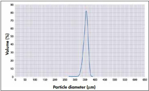
Figure 2. Typical size distribution of microspheres made by laminar flow drip-casting with a 150-µm vibration nozzle. (Credit: Brace GmbH.)
A wide range of shell materials can be used with this highly scalable technology. The processes combine low space and energy consumptions with high throughput and very high flexibility of the feed materials to be used as well as low maintenance. The process can be tailored to meet all necessary requirements, such as good manufacturing practice (GMP), good laboratory practice (GLP), FDA, pharmaceutical, food, nuclear, chemical, or other industrial standards.
Particles can be made from a wide variety of materials, and process parameters vary depending on the application and raw materials. Figure 3 shows the basic principle for making particles via the melt process. A liquid feed is pumped from a feed tank (3) to the nozzle head (5), where the vibrating device (2) induces breakup of the flow into uniform droplets, which surface tension forms into spheres. The droplets solidify as they fall through the solidification area (9) by cooling, chemical reaction, or drying, depending on the material or solidification system. Process control is maintained visually with a stroboscopic lamp or with a camera (for remote control) and with electronics (1). For melt-processing applications—for example, silicon for solar cells—a heating chamber attaches to the top of the unit. In other processes, where the starting materials are powders—for example, for proppant production—the process runs at room temperature and droplets solidify in a reactive solution. Other materials, including metal solutions for various applications, such as catalyst carriers and nuclear fuel, make use of a sol–gel reaction, where the metal solution solidifies by reacting with gas during the fall.
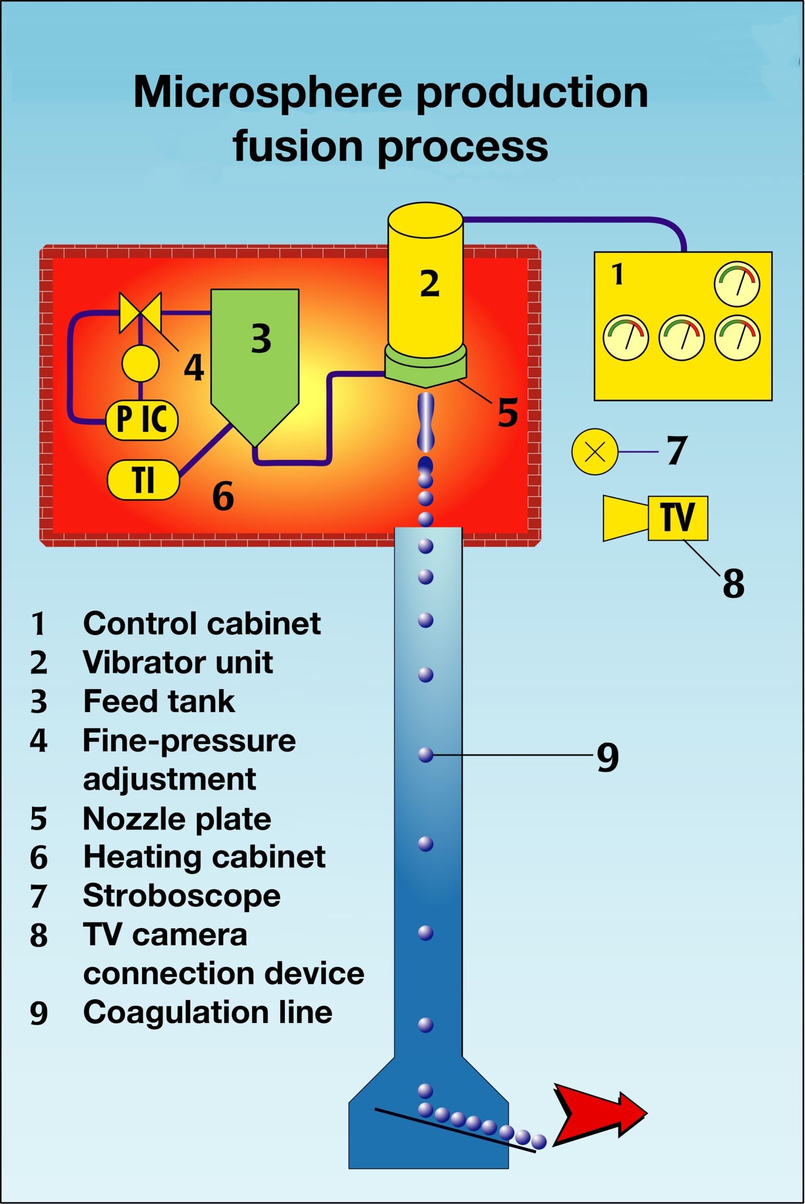
Figure 3. Schematic diagram of fusion process for microsphere production. (Credit: Brace GmbH.)
Theoretical basis
Liquid extruded through an orifice by gravitational force alone produces droplets with diameter xt determined by the viscosity and surface tension of the liquid and not related to the diameter of the orifice. However, as the flow rate accelerates, there is a minimum flow rate for the transition from “dripping” to “flowing,” where flowing refers to a constant flow of liquid extruding from the nozzle. This minimum flow or critical flow rate is a function of the surface tension, viscosity, and nozzle orifice.
When the liquid flow reaches a critical speed vcrit, surface tension compresses the liquid thread and leads to an instability with a minimal wavelength of λreal = 4.5D, where D is the diameter of the orifice.
This instability disrupts the thread into liquid cylinders that surface tension forms into spherical droplets. Assuming an identical volume for droplet and cylinder, an ideal droplet diameter corresponds only to the nozzle diameter according to xt = 1.89D, assuming that the flow is laminar and within the laminar flow breakup range of the Ohnsorge–Reynolds plot (Figure 4). This drip-casting is a two-step process: First, it generates a laminar flow with a speed determined by the material properties; and, second, it forms a spherical droplet by the surface tension of the material, where the diameter of the droplet is a function of the nozzle diameter.
Figure 4. Ohnsorge–Reynolds plot showing region where liquid laminar flow can be broken into regular droplets (We is Weber number, Re is Reynolds number, and Oh is Ohnsorge number). (Credit: Brace GmbH.)
Disruption of the flow can lead to so-called satellite droplets that have a diameter of xS ≥ 0.1xt. Their quantity is comparably small (0.1%–1%), but they increase the total surface area of the spray. Because droplet diameters have various falling speeds, the distance the droplets fall is no longer constant, and droplets can coalesce. This leads to the “noseforming” found in nonoptimized processes. Viscosity, for all practical purposes, ranges between 10–3 and 104 N/m. Consequently, the Ohnsorge number (Oh) can range over seven orders of magnitude. Therefore, the effect of the viscosity is quite high. Materials with higher viscosity produce longer instability wavelengths and, therefore, larger droplets.
The maximum viscosity usable for the laminar flow breakup process is determined by the requirement for laminar flow to be obtained. In practical terms, an upper limit of 5,000 mPa·s is reasonable.
Applying external vibration to the flow avoids problems, such as satellite formation and noseforming. The vibration can be in the direction of the flow or perpendicular to it. It controls the flow breakup and leads to uniform droplets determined by the frequency of the external vibration.
It is not important how the vibration is brought into the liquid (vibration of the nozzle or the liquid, vibration in the flow axis or perpendicular to it). However, experience shows that a vibrating nozzle with a vibration in the flow axis performs better.
Microspheres for silicon solar cells—Two approaches
The majority of solar cells available commercially are made via a metallurgic route, which is inexpensive, uncompliated, and inefficient. In some countries, including Germany, electricity generated by solar energy is highly subsidized, allowing for an underwritten economic profit.
One disadvantage of flat-panel solar cells is that they must angle toward the sun for optimum performance. Another drawback is that they are packed into layers of polymers, glass, and protective housings, which makes the panels thick, decreases the energy yield, and leads to end-of-life recycling problems. Spherical solar cells—each of which is a single round solar cell—could be a possible solution to these problems.
Because of the round shape, solar cell spheres are independent of the incident angle of the sunlight—any angle will do for high energy efficiency. In addition, such spherical particles resist mechanical stress, and, thus, they do not need to be protected. A unimodal size distribution of silicon microspheres prepared from molten silicon can be made into tough, efficient, lightweight solar panels. By optimizing cooling parameters, it is even possible to produce single-crystal or almost-single-crystal microspheres, which decreases downstream processing costs dramatically.
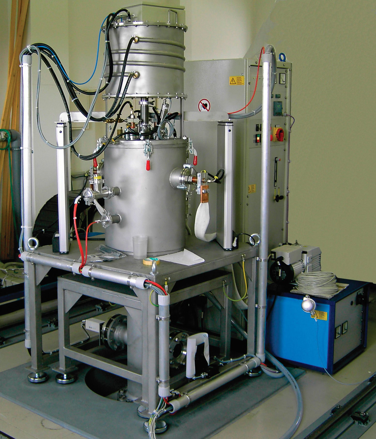
Figure 5. Laboratory unit for drip-casting microspheres from molten silicon. (Credit: Brace GmbH.)
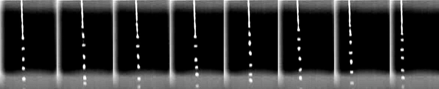
Figure 6. Drip-casting of molten silicon for solar cell application. (Credit: Brace GmbH.)
Figure 5 shows a laboratory unit for making silicon spheres. Figure 6 shows how drip-casting forms droplets of silicon microspheres. The embodied energy of silicon microspheres is low compared with other processes, because the silicon has to be molten once (unlike ribbon or tube-pulling processes where a ribbon or tube is pulled from a melt of silicon), and the purity is very high. The process and the spherical shape of the particles allow for efficient and fast continuous handling. Finally, the drip-casting process converts almost 100% of the raw material into microspheres, which decreases in-process recycling costs to previously unseen values.
Although the melt process is a good way to produce spherical silicon microspheres for solar cells, it is a high-temperature process, and molten silicon is very corrosive. An alternative approach combines fine silicon powder left over from the metallic silicon foundry process with a binder in a slurry. Byproduct silicon powders have particle sizes <100 µm and are expensive to discard, but are ideal for engineering into microspheres.
Suspensions contain about 5 wt% binder and are prepared at room temperature. Microspheres are made by drying silicon–binder–water spheres and sintering them at 1,300°C–1,450°C to remove the binder and densify the initial fine powders into large, high-purity silicon microspheres. High-purity spheres are possible because the purity of the binder determines the purity of the resulting silicon microsphere.
The binder process offers several advantages over a melt unit: Throughput is much higher, it operates at room temperature or slightly above, it is easier to control the size of the spheres, and it is easier to avoid impurities.
The carbon content of the powders is not necessarily higher than in “pure” silicon spheres. However, by choosing proper sintering parameters, carbon content can be decreased to a level suitable for solar cell manufacturing.
In summary, both processes offer unique advantages. The melt process is optimal when molten silicon is available. It is deposited easily into a drip-casting unit without energy-wasting solidification and remelting steps. Also, the melt process can accommodate larger scraps or material with nonuniform shapes for a fast and efficient route to produce microspheres.
On the other hand, in situations where space is insufficient for large-scale production, or when fine silicon dust powder is available, the binder process has the advantage. As a low-energy, low-space-consuming process, it can be installed almost anywhere. However, the raw silicon needs to be available as fine powder.
Nuclear fuel microspheres
Nuclear fission of uranium, thorium, and plutonium is an important source of CO2-free energy. One system—the pebble bed high-temperature reactor—has an extremely low risk of a core melt, can incorporate (and thus remove) weapons-grade plutonium, and produces significantly less waste than pressure or steam reactor nuclear power stations. The system uses “tennis-ball-shaped” fuel instead of rods. The nuclear fuel pebbles, with a diameter of 60 mm, contain about 40,000 microspheres of UO2 or ThO2 with 300-µm diameters (Figure 7). These fuel microspheres also can contain plutonium, which degrades during the course of the fission process and returns into the fuel cycle.
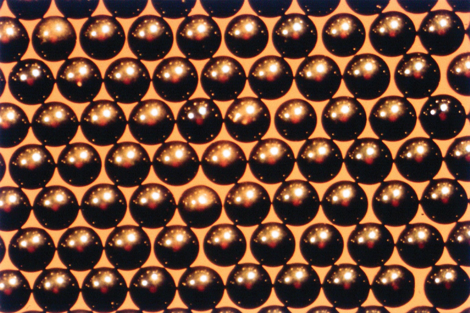
Figure 7. Uranium dioxide microspheres (as sintered). (Credit: Brace GmbH.)
A uranium- and thorium-based sol–gel process produced the microspheres shown in Figure 7. Nuclear fuel microspheres now can be made using a binder process. The binder process offers several advantages, including easier process control and a more generalized approach.
Some metals form hydroxide sols. Low-viscosity sols, such as zirconium, hafnium, or aluminum hydroxide, stabilized with organic compounds, such as polyalcohol, or with pore formers, such as urea, extrude easily through a nozzle system. A gas reaction with ammonia transforms sol to gel during the initial falling period. After this initial solidification, the gel solidifies completely in an ammonia solution.
Starting sols can be made from any metal solution where the metal forms an insoluble hydroxide (preferably one that peptisizes during gel formation). For these solutions, the pH is adjusted close to the gelation point to accelerate and control the gas reaction more precisely. If gel formation of the solution is not strong enough, poly(vinyl alcohol) (PVA) or other organics can be added and removed completely in later process steps.
Sol–gel synthesis of ThO2 and UO2 microspheres (“kernels”) starts with solutions of thorium nitrate and uranyl nitrate with PVA as a gelling aid. Gelling after molding has to be adjusted exactly. A short presolidification with gaseous ammonia is the first step to obtain a permeable, solidified shell for subsequent reaction in an ammonia solution. The entire solidified sphere must be porous to allow diffusion of water and NH4NO3 during washing and drying of the spheres. The purity advantages of the sol–gel process diminish somewhat by the necessary extensive washing of the beads to remove traces of counterion nitrates and carbonates, which degrade during the heat-treatment steps and fracture the microspheres. Also, using ammonia solutions and ammonia gasses poses environmental issues that have to be fully handled, for example, with sensors, air scrubbers, and operator training.
Alternatively, we developed a binder process for producing actinide oxide fuel microspheres without using ammonia gas and ammonia solutions that involves drip-casting a fine powder suspension of the metal oxide. The starting powder should have a sufficiently small grain size—d90 < 3 µm is preferred—and a temporary binder, such as a hydrocolloid, PVA, or similar material. The solidification route depends on the binder, and it is important to minimize the risk of adding impurities. For example, a suspension with an alginate binder and solidified with CaCl2 could result in a calcium content that might cause problems during fuel recycling. However, a range of technical solutions to this problem is available.
Both synthesis processes require washing of the microspheres to remove unwanted components. For the sol–gel case, the unwanted constituents are mainly nitrates, carbonates, and chlorides, whereas for the binder process, these are excess reactive ionic solutions plus their corresponding chloride counterions. The initial washing uses purified water. It is followed by one or more alcohol washes—usually isopropyl alcohol—that remove the water, harden the microspheres, and decrease the volume.
The washed microspheres are dried and calcined in air to remove residual organics, such as liquefiers and binders. Sintering in hydrogen decreases the particle size to about half that of the green microspheres. The sintering results in a density of 96%–99% of the theoretical density of the oxide ceramic (Figure 8).
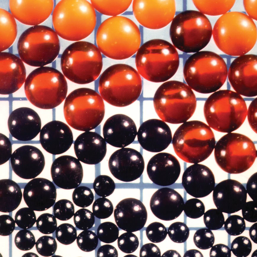
Figure 8. Nuclear fuel microsphere size reduction during process from as-formed (topmost), dried, calcined, and sintered (bottom). (Credit: Brace GmbH.)
Microsphere proppants for oil and natural gas recovery
Although the term “fossil energies” gives the impression of an outdated technology, fossil-based energy provides for our living standards today. Besides energy, gas and oil also provide the basis for many nonenergy products.
The amount of available gas and oil is finite, and much of what remains is trapped in rock formations that require new technologies for economical recovery. The North American shale gas reservoirs are a current focus of attention, but natural-gas shale areas in Europe and Asia and oil reservoirs at the sea bed level also are being developed.
Technology called hydrofracturing—or fracking—is used to open up and provide a porous pathway to extract the oil and gas from shale reservoir rock. A water mixture under high pressure is forced into the borehole and creates fissures in the rock formation. However, enormous geostatic pressure on the rock will cause the fissures to close quickly unless they are held open with particulates known as proppants. Proppants are a major economic factor in hydrofracturing technology. For example, chemicals that decrease the viscosity of oil and facilitate its flow to the surface work more efficiently when used in conjunction with proppants.
Typically, sand proppants hold the fissure open to allow natural gas and oil to flow to the surface as the water pressure recedes. Although sand proppant is sieved for proper sizing (Figure 9 (a)), its irregular form fills the fissures, and its crush resistance is low, both of which can decrease the possible borehole yield.
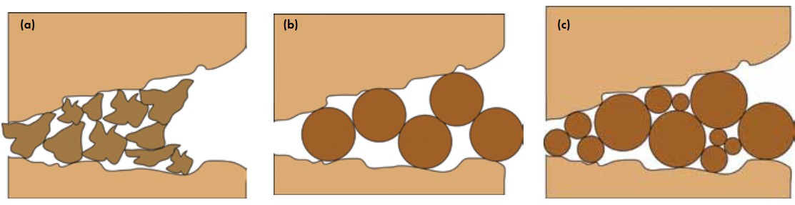
Figure 9. (a) Irregularly-shaped sand proppants can pack too tightly into a shale fissure. (b) Unimodal proppants hold open a fissure, but do not fill it efficiently. (c) Optimized mixture of variously-sized microspheres keeps fissures open. (Credit: Brace GmbH.)
As the demand for high-quality proppants increased, suppliers investigated artificial or synthetic particles, for example, Al2O3 microspheres, which are very stable. However, the raw-material price was higher than other natural sources. Thus, development focused on alternative raw materials. Researchers found a wide selection of natural materials, mostly based on bauxite or clay materials, that offered a good compromise between stability and cost. Unfortunately, they were supplied as powder and not as uniformly-sized particles.
Drip-casting processes can be used to manufacture an optimized, perfectly unimodal distribution of ceramic microspheres with high crush strength on a large scale at economical prices. Also, drip-casting is flexible enough to accommodate variations in the raw-material supply, whether they occur from differences in the same mine or between suppliers. The production process has the advantage of scalability: All process parameters are identical between small laboratory-sized units up to large-scale production units with more than 20,000 kg/h capacity.
Vibrational drip-casting processes can produce between 1,000 and 20,000 kg/h of ceramic or clay-type proppants. The size control during processing helps increase the borehole yield. If a single-sized particle is used, fissures can be held open to the specific size of the particles (Figure 9 (b)), leaving a large free area. Because unimodal spheres cannot enter the entire fine structures of fissures, small gaps reclose quickly. A mixture of two or more unimodal, spherical proppants allows the smaller particles to settle in the fine-scale regions of fissures and the larger ones to fill and hold open the wider part of the cracks (Figure 9 (c)). This decreases the specific gap between the microspheres, and smaller microspheres fill the spaces between. However, there is greater total void space and more gas or oil flows from the fissures.
The required ratio of particle sizes is specific. Theoretical calculations show that a particle-size ratio of 1:5 to 1:8 gives the best results. In the field, a ratio of 1:6 or 1:6.5 is used widely. Another advantage of spherical particles is the ceramic types tend to break in stable fractions of a sphere and continue to prop the fissure partly open. Sand proppants, in contrast, crumble to fine, irregular particles and close the fissure completely.
In addition to size, particle density is a factor that determines how deep a microsphere can penetrate a fissure. The tendency is to investigate low-density particles—about 1 g/cm3, which is approximately the density of water—because it is the water that pushes them into the fissure. Microsphere density can be tailored using the drip-casting processes by producing highly porous or hollow particles (Figure 10). Ceramics are not the only option for proppants, and several organic compositions are being investigated.
Figure 10. Hollow ceramic microspheres. (Credit: Brace GmbH.)
Conclusion
Energy and energy-related processes present challenges. Some can be solved by using highly spherical, unimodal, and controlled size distribution particles, such as microspheres and microcapsules. Both types of particles can be made by laminar flow drip-casting with a vibrational nozzle. The process offers the opportunity for total control over particle size, flexibility to manufacture a wide variety of raw materials into microspheres, and scalability. Already, many industries rely on them, offering better products to sustain a better world for everyone.

Related Articles

Bulletin Features
Emerging Professionals: Science for Society & Future Focus
One small tweak to the lens of materials research, one giant leap for mankind By Rishabh Kundu and Ryan C. Eaton One of the clearest existential threats facing humanity is anthropogenic climate change. The dire consequences to ecological stability and human prosperity if the status quo is maintained are thoroughly…

Bulletin Features
Emerging Professionals: Research Articles
Experiential learning: Developing the next generation of engineers By Ryan Eaton When a measure becomes a target, it ceases to be a good measure. Goodhart’s law, coined in reference to monetary policy, is readily applicable to engineering education. When students begin optimizing their study habits to pass an exam rather…

Bulletin Features
Durable and programmable metasurfaces enabled by phase change materials
Controlling light with high spatial precision enables technologies ranging from imaging and sensing to communications. Traditionally, optical components such as lenses and filters rely on bulk materials and fixed geometries, which limit their ability to adapt dynamically. Metasurfaces offer a fundamentally different approach. These materials consist of planar arrays of…